 المقاولين,قاطع الدائرة,العاكس للطاقة الشمسية,عداد كهرباء,البطاريات الشمسية

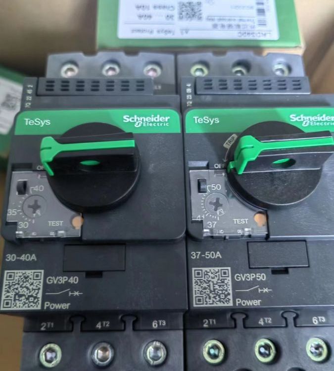


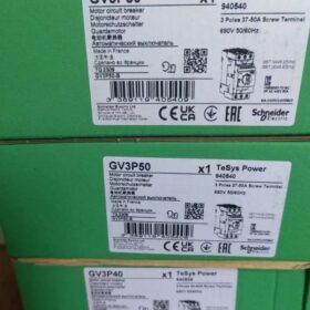
Schneider GV3P50 Motor Circuit Breaker Product Introduction, خطوات التثبيت & Cross-Brand Model Comparison
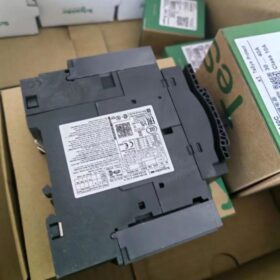
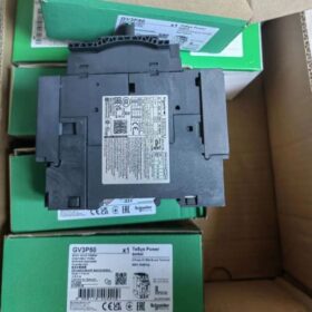
Schneider GV3P50 is a motor circuit breaker belonging to the TeSys GV3 series, mainly used for the protection and control of electric motors.
المعلومات الأساسية
نوع المنتج: Thermomagnetic motor circuit breaker
رقم القطب: 3 أقطاب
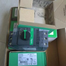
Control Type: Knob control
تصنيف جهد التشغيل: 690فولت تيار متردد 50/60 هرتز
التصنيف الحالي: 50أ
Thermal Protection Adjustment Range: 37-50أ
تيار الرحلة المغناطيسي: 700أ
ميزات الأداء
وظائف الحماية: Equipped with thermomagnetic tripping function, which can effectively protect the motor from overload and short circuit. It also has phase failure protection function, which can act in a timely manner when the motor has a phase failure fault to protect the motor.
كسر القدرة: The ultimate breaking capacity (ICU) is 100kA at 230/240V AC; 50kA at 400/415V AC and 440V AC; 12kA at 500V AC; 6kA at 690V AC.
Durability: Both mechanical and electrical durability reach 50,000 دورات (AC-3 duty at 415V), enabling long-term stable operation in industrial environments.
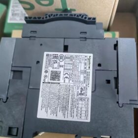
طريقة التركيب: Supports 35mm symmetrical DIN rail mounting and panel mounting with 3 M4 screws for easy installation.
مجالات التطبيق
Suitable for various motor application scenarios such as workshops, machinery manufacturing, and construction installation, and can reliably protect motors with a power of up to 22kW (at 400V AC).
Installation Steps for Schneider GV3P50 Motor Circuit Breaker
Schneider GV3P50 is a thermomagnetic motor circuit breaker of the TeSys GV3 series, supporting two mainstream mounting methods: 35mm standard DIN rail mounting and panel screw mounting. Installation must comply with industrial electrical construction specifications, focusing on safe power off, mechanical fixation, standard wiring, and post-installation verification. The following is a detailed step-by-step operation (including pre-installation preparation, two fixation methods, الأسلاك, verification and precautions), suitable for the installation scenario of distribution cabinets/control cabinets in industrial sites.
- التحضير قبل التثبيت
1.1 Safety Prerequisite
All power supplies of the circuit to be installed must be disconnected, and power-off signs must be posted. Operate only after confirming that there is no voltage in the circuit to avoid electric shock.
1.2 Inspection of Product and Accessories
Check that the GV3P50 body has no damage, the wiring terminals have no oxidation, the knob (ON/OFF/reset) operates smoothly, and the tripping mechanism has no jamming;
Verify that the parameters on the product nameplate (rated voltage 690V, rated current 50A, thermal protection 37-50A) match the on-site power supply and motor;
Prepare supporting accessories: 35mm symmetrical DIN rail (for rail mounting), M4 stainless steel screws (for panel mounting, Schneider original torque-adapted accessories), crimp terminals (copper core).
1.3 إعداد الأداة
Phillips screwdriver (PH2), وجع عزم الدوران (adapted to 2.5N·m), متجرد الأسلاك, المتر المتعدد, rail cutting/fixing pliers, drilling machine/electric drill (for panel mounting drilling).
1.4 Installation Environment Confirmation
The installation location must meet the protection requirement of IP20 and above (inside distribution cabinet/control cabinet), with an ambient temperature of -25℃~+60℃. Keep away from heat sources, الغبار والغازات المسببة للتآكل, ensure a flat mounting surface, and reserve operation and heat dissipation space (≥5mm on both sides, ≥10mm on the top and bottom).
- Method 1: 35mm Standard DIN Rail Mounting (مُستَحسَن, Mainstream Method in Distribution Cabinets)
GV3P50 adopts a DIN rail snap-in design, adapted to the industrial universal 35mm symmetrical steel rail, with easy installation and convenient later disassembly and maintenance. The steps are as follows:
- Fix the DIN rail: Fix the 35mm standard DIN rail on the mounting plate of the distribution cabinet with screws. The rail must be horizontal, firm and without warpage. The length of a single rail is adjusted according to the number of installed devices. The rail occupation length of the GV3P50 body is about 45mm;
- Snap in the circuit breaker: Align the bottom buckle of the GV3P50 body with the upper edge of the DIN rail, press the body down and push it forward slightly until a “انقر” sound is heard to confirm that the bottom buckle is locked to the rail;
- Lock the top buckle: Pull the top buckle wrench (small side paddle) of the GV3P50 body to lock the top buckle to the lower edge of the rail to prevent the circuit breaker from loosening in a vibrating environment;
- Mechanical fixation verification: Gently shake the circuit breaker left and right, up and down by hand to confirm that there is no relative displacement between the body and the rail, and the knob operates without jamming (after rail mounting, the circuit breaker can slide slightly along the rail; if the position needs to be fixed, rail end caps can be installed at both ends of the rail).
- Method 2: Panel Screw Mounting (Suitable for On-Site Independent Control Box/Operation Panel Mounting)
GV3P50 supports panel fixation with 3 مسامير M4, adapted to a panel thickness of 1~4mm (2~3mm cold-rolled steel plate/plastic panel is recommended). The steps are as follows:
- Mark the mounting hole positions: Attach the GV3P50 body tightly to the mounting panel, and mark the positions of the 3 M4 mounting holes on the body with a marker (distributed in a triangle for precise positioning);
- Drill holes on the panel: Drill holes according to the marked positions with a hole diameter of φ4.2mm (slightly larger than M4 screws to avoid thread slipping). Clean the burrs on the panel after drilling to prevent scratching the wires or hands;
- Thread the screws for fixation: Pass the M4 screws into the mounting holes from the outside of the panel, align with the threaded holes of the GV3P50 body, initially tighten with a Phillips screwdriver, and then tighten to 2.5N·m with a torque wrench (the torque specified by the original factory to prevent damage to terminals/body due to excessive tightening force);
- Firmness check: After tightening, pull the circuit breaker body by hand to confirm no looseness, and the part of the knob exposed on the panel operates smoothly without panel jamming.
- Standard Wiring Operation (Core Step to Avoid Poor Contact/Faults)
GV3P50 is a 3-pole circuit breaker, with the upper end as the incoming terminal (L1/L2/L3) and the lower end as the outgoing terminal (T1/T2/T3). Strictly follow the principle of “upper incoming and lower outgoing”, adapted to copper core wires. Direct wiring of aluminum core wires is prohibited (copper-aluminum transition terminals are required). The steps are as follows:
- Wire preprocessing: Select the adapted copper core wire according to the on-site current-carrying capacity (recommended wire cross-section for GV3P50: 10~16mm²), strip the wire insulation layer with a wire stripper, and the wire stripping length is 8~10mm (excessively exposed core wire is prone to short circuit, and insufficient length is prone to poor contact);
- Crimp the wiring terminals: Crimp the stripped wire core with a cold-pressed copper terminal (tubular/fork type, adapted to 10~16mm² wires) firmly without loose core wires;
- Phase-separated wiring: Connect the three-phase power incoming wires to the L1/L2/L3 terminals respectively, and the motor outgoing wires to the T1/T2/T3 terminals respectively with consistent phase sequence correspondence (to prevent motor reverse rotation; if reverse rotation is needed, the phase sequence can be adjusted on the outgoing side);
- Torque tightening of terminals: Tighten the wiring terminal screws to 2.5N·m with a torque wrench (unified torque for M4 terminals of the GV3 series). After tightening, pull the wire gently to confirm no looseness and no exposed core wires at the terminals;
- Housing grounding: Reliably connect the metal housing grounding terminal of GV3P50 (if equipped, φ4 grounding hole on the side) to the on-site protective ground wire (PE wire). The cross-section of the grounding wire is ≥4mm² copper core to prevent housing electric leakage.
- Overall Post-Installation Verification
After the completion of installation and wiring, mechanical and electrical double verification must be carried out, and power can only be supplied after confirming no problems. The steps are as follows:
- Mechanical action verification: Manually operate the knob repeatedly from OFF→ON→OFF for 2~3 times to confirm that the closing and opening are in place. The knob points to the red mark in the ON state and the green mark in the OFF state, and the trip reset button does not pop up;
- Electrical on-off verification: Measure with the resistance gear of a multimeter. In the ON state of the circuit breaker, the three groups of terminals L1-T1, L2-T2 and L3-T3 are connected respectively (resistance is close to 0); in the OFF state, the three groups of terminals are all disconnected (infinite resistance), with no phase-to-phase short circuit or terminal grounding;
- Protection mechanism check: Gently press the trip test button (امتحان) on the body to confirm that the circuit breaker can trip normally and the knob bounces to the OFF position. Then press the reset button to close again, and the trip mechanism acts sensitively.
- Key Installation Precautions
- Maintain power-off operation throughout the process. Reconfirm that there is no short circuit in the circuit and no reverse wiring before power transmission. It is forbidden to wire/disconnect the wiring when the circuit breaker is in the closed state;
- The thermal protection setting value must be adjusted according to the actual rated current of the motor (the adjustment range of GV3P50 is 37~50A). Rotate the thermal protection adjustment knob on the side of the body to align with the corresponding current scale, and do not adjust beyond the range;
- Reserve operation space at the installation location. The knob and trip/reset button must be exposed for convenient on-site operation and fault reset, and must not be blocked by other devices in the distribution cabinet;
- When multiple GV3 series circuit breakers are installed side by side, the spacing between adjacent devices is ≥5mm to ensure heat dissipation and avoid affecting the protection performance due to excessive temperature rise;
- It is forbidden to connect multiple wires to the wiring terminal at the same time. If parallel wiring is needed, use a special parallel terminal to ensure the contact area and prevent heating due to poor contact;
- If there is strong vibration on site (such as beside machine tools and pumps), install rail fixing clamps for rail mounting, and select anti-loosening M4 screws (spring washer + flat washer) for panel mounting to prevent the circuit breaker from loosening;
- It is forbidden to modify the circuit breaker body without authorization (such as disassembling the tripping mechanism and replacing terminals), otherwise the original Schneider protection performance will be lost and the protection will fail.
Supplementary: Installation Dimension Reference
The installation dimensions of the GV3P50 body (without accessories) نكون: 45مم (دبليو) × 87mm (ح) × 74mm (د). Installation space must be reserved according to these dimensions for both mounting methods. If auxiliary contacts (such as GVAE11) need to be installed, the width will increase and the space must be reserved synchronously.
Cross-Brand Model Comparison Scheme for Schneider GV3P50 Motor Circuit Breaker
The following are the mainstream brand alternative models of GV3P50 (3 أقطاب, thermomagnetic type, 37-50أ, adapted to 22kW/400V motor), covering the selection of international first-tier and cost-effective domestic brands. Focusing on the four dimensions of function matching, installation compatibility, breaking capacity and cost-effectiveness, it is convenient for procurement replacement and system upgrade decision-making.
- Core Benchmark Parameters of GV3P50 (Comparison Basis)
| عنصر المعلمة | Technical Specification |
| نوع المنتج | Thermomagnetic motor circuit breaker (manual knob control) |
| رقم القطب | 3 أقطاب |
| Thermal Protection Adjustment Range | 37-50أ |
| تصنيف جهد التشغيل | 690فولت تيار متردد 50/60 هرتز |
| كسر القدرة (ICU) | 50kA@400V AC, 100kA@230V AC |
| Magnetic Trip Multiple | 14脳In (about 700A) |
| Adapted Motor Power | 22كيلوواط (at 400V AC) |
| طريقة التركيب | 35mm standard DIN rail/panel mounting (45عرض ملم) |
| وظائف الحماية | Triple protection against overload, short circuit and phase failure |
- Overall Cross-Brand Alternative Model Comparison Table (Priority Ranking)
The table is grouped by international first-tier brands → cost-effective domestic brands, marking key differences and applicable scenarios:
| ماركة | النموذج البديل | Thermal Protection Range | كسر القدرة | Installation Dimension | Core Matching Degree | Cost Reference | Applicable Scenario |
| Schneider Own Series | GV3P501 (with EverLink terminals) | 37-50أ | 50kA@400V | 45عرض ملم | ★★★★★ (original factory same specification) | 100% | Original system expansion/spare part replacement |
| ايه بي بي | MS495-50 | 37-50أ | 50kA@400V | 45عرض ملم | ★★★★★ | 95% | Industrial automation system, matching with ABB contactors |
| سيمنز | 3RV5041-4HA10 | 36-50أ | 50kA@400V | 55عرض ملم (S2 specification) | ★★★★☆ | 90% | Siemens PLC control system, need to reserve an additional 5mm width |
| 3RV6041-4HA10 | |||||||
| Eaton Moeller | DIL00-50 | 37-50أ | 50kA@400V | 45عرض ملم | ★★★★★ | 85% | الآلات الثقيلة, adapted to Eaton contactor combinations |
| DIL0-50 | |||||||
| شينت | NDM2-63M/3300 | 37-50أ | 50kA@400V | 45عرض ملم | ★★★★☆ | 40% | General industrial scenarios, cost performance first |
| Set to 37-50A | |||||||
| لذيذ | CDM3v-63C/33002 | 37-50أ | 50kA@400V | 45عرض ملم | ★★★★☆ | 35% | Building electrical/small machinery, first choice for domestic replacement |
| Set to 37-50A | |||||||
| تشانغشو التبديل | CM3-63M/3300 | 37-50أ | 50kA@400V | 45عرض ملم | ★★★★☆ | 45% | High-end domestic replacement, adapted to harsh working conditions |
| Set to 37-50A |
- Detailed Parameter Comparison of Key Models (In-Depth Selection Reference)
3.1 International First-Tier Brands (Complete Function and Performance Matching)
ABB MS495-50
الميزات الأساسية: Exact same dimension as GV3P50 (45عرض ملم), consistent thermomagnetic tripping curve, supporting dual mounting of rail/panel, and equivalent phase failure protection function;
Terminal Specification: Adapted to 10-16mm² copper wires with a torque of 2.5N·m, compatible with the wiring tools of GV3P50;
توافق الملحقات: Can be equipped with ABB auxiliary contacts (such as MS132 series), compatible with the accessory mounting position of GV3P50;
Advantage: Excellent synergy with ABB contactors (AX series), suitable for the upgrade and replacement of the original ABB system.
Siemens 3RV5041-4HA10
الميزات الأساسية: Thermal protection range of 36-50A (covering GV3P50), breaking capacity of 50kA@400V, standard configuration of SIRIUS series;
Differences: 55عرض ملم (10mm wider than GV3P50), need to adjust the installation layout, magnetic trip multiple of 13×In (slightly lower than 14×In of GV3P50);
Advantage: Strong digital communication adaptability with Siemens PLC (S7 series), suitable for production lines with high automation level.
Eaton DIL00-50
الميزات الأساسية: 45mm standard width, consistent thermomagnetic tripping characteristics with GV3P50, mechanical life of 50,000 مرات (same as GV3P50);
Special Advantage: Supports the “plug-and-play” accessory system, which can quickly install auxiliary contacts/alarm modules for convenient maintenance;
Adaptation: Perfectly matched with Eaton Icon series contactors, suitable for OEM equipment supporting.
3.2 Cost-Effective Domestic Alternatives (Functional Equivalence, تحسين التكلفة)
Chint NDM2-63M/3300 (Set to 37-50A)
الميزات الأساسية: Thermomagnetic tripping, complete triple protection functions, breaking capacity of 50kA@400V, fully meeting the GB14048.4 standard;
Cost Advantage: The price is about 40% of the Schneider original factory, suitable for batch replacement and new economical projects;
تثبيت: Universal for 35mm DIN rail, the panel mounting hole positions are consistent with GV3P50 without re-drilling.
Delixi CDM3v-63C/33002 (Set to 37-50A)
الميزات الأساسية: Peak series motor protection circuit breaker with thermal protection accuracy of ±5% (close to the level of international brands);
Added Value: Built-in surge suppression function, suitable for industrial scenarios with large power grid fluctuations;
التوافق: The wiring terminal specification is the same as GV3P50, which can directly replace the original wiring.
- Key Precautions for Replacement and Selection
4.1 Installation Compatibility Check
Prioritize models with 45mm width (such as ABB MS495-50, Eaton DIL00-50) without adjusting the layout of the distribution cabinet;
If the Siemens 3RV5041 series (55عرض ملم) is selected, confirm that the spacing between adjacent devices is ≥10mm to avoid poor heat dissipation.
4.2 Protection Characteristic Matching Principle
The thermal protection range must cover 37-50A, and fixed-value 50A models (such as some domestic simplified versions) are not allowed;
The magnetic trip multiple should be between 12-14×In to ensure the reliability of short circuit protection;
Phase failure protection is a necessary function to avoid motor burnout due to phase loss (this function may be omitted in some economical models).
4.3 Wiring and Accessory Adaptation
The wiring terminals must be adapted to 10-16mm² copper wires with a unified torque of 2.5N·m to prevent heating due to poor contact;
The mounting position of auxiliary contacts (لا/NC) must be compatible with the original system to avoid redesign of the secondary circuit.
4.4 Cost-Effectiveness Balance
Expansion of the original Schneider system: Prioritize GV3P501 (original factory same specification, 100% compatibility);
Cross-brand replacement: ماركات عالمية (ABB/MS495, Siemens/3RV5041) are suitable for key equipment, والعلامات التجارية المحلية (Chint/NDM2, Delixi/CDM3v) are suitable for general loads, with a cost reduction of about 60%.
- Recommended Replacement Combination Schemes
| سيناريو التطبيق | Preferred Recommended Model | Replacement Advantage |
| Key equipment (such as main motor of production line) | ABB MS495-50 | Consistent performance, strong brand synergy and high reliability |
| Automation system (equipped with PLC control) | Siemens 3RV5041-4HA10 | Good communication adaptation and complete remote monitoring functions |
| Batch replacement (such as workshop equipment transformation) | Chint NDM2-63M/3300 | Optimal cost, complete function matching and short delivery cycle |
| Spare parts for the original Schneider system | GV3P501 | 100% compatibility without any adjustment |
| MCB – 1 POLE – 10 أ – 6 KA – ACTI9 – IC60N | شنايدر إلكتريك | A9F44110 |
| MCB – 1 POLE – 25 أ – 6 KA – ACTI9 – IC60N | شنايدر إلكتريك | A9F44125 |
| MCB – 2 POLE – 6 أ – 6 KA – ACTI9 – IC60N | شنايدر إلكتريك | A9F44206 |
| MCB – 2 POLE – 10 أ – 6 KA – ACTI9 – IC60N | شنايدر إلكتريك | A9F44210 |
| MCB – 2 POLE – 25 أ – 6 KA – ACTI9 – IC60N | شنايدر إلكتريك | A9F44225 |
| MCB – 3 POLE – 6 أ – 6 KA – ACTI9 – IC60N | شنايدر إلكتريك | A9F44306 |
| MCB – 3 POLE – 63 أ – 6 KA – ACTI9 – IC60N | شنايدر إلكتريك | A9F44363 |
| MCB – 4 POLE – 6 أ – 6 KA – ACTI9 – IC60N | شنايدر إلكتريك | A9F44406 |
| MCB – 4 POLE – 20 أ – 6 KA – ACTI9 – IC60N | شنايدر إلكتريك | A9F44420 |
| MCB – 4 POLE – 25 أ – 6 KA – ACTI9 – IC60N | شنايدر إلكتريك | A9F44425 |
| MCB – 4 POLE – 32 أ – 6 KA – ACTI9 – IC60N | شنايدر إلكتريك | A9F44432 |
| MCB – 4 POLE – 40 أ – 6 KA – ACTI9 – IC60N | شنايدر إلكتريك | A9F44440 |
| MCB – 4 POLE – 50 أ – 6 KA – ACTI9 – IC60N | شنايدر إلكتريك | A9F44450 |
| MCB – 4 POLE – 63 أ – 6 KA – ACTI9 – IC60N | شنايدر إلكتريك | A9F44463 |
| MCB – 1 POLE – 6 أ – 6 KA – ACTI9 – IK60 | شنايدر إلكتريك | A9K24106 |
| MCB – 1 POLE – 10 أ – 6 KA – ACTI9 – IK60 | شنايدر إلكتريك | A9K24110 |
| MCB – 1 POLE – 16 أ – 6 KA – ACTI9 – IK60 | شنايدر إلكتريك | A9K24116 |
| MCB – 1 POLE – 20أ – 6 KA – ACTI9 – IK60 | شنايدر إلكتريك | A9K24120 |
| MCB – 2 POLE – 10 أ – 6 KA – ACTI9 – IK60 | شنايدر إلكتريك | A9K24210 |
| MCB – 2 POLE – 16 أ – 6 KA – ACTI9 – IK60 | شنايدر إلكتريك | A9K24216 |
| MCB – 2 POLE – 20أ – 6 KA – ACTI9 – IK60 | شنايدر إلكتريك | A9K24220 |
| MCB – 2 POLE – 25أ – 6 KA – ACTI9 – IK60 | شنايدر إلكتريك | A9K24225 |
| MCB – 2 POLE – 32أ – 6 KA – ACTI9 – IK60 | شنايدر إلكتريك | A9K24232 |
| MCB – 2 POLE – 40أ – 6 KA – ACTI9 – IK60 | شنايدر إلكتريك | A9K24240 |
| MCB – 2 POLE – 63أ – 6 KA – ACTI9 – IK60 | شنايدر إلكتريك | A9K24263 |
| MCB – 3 POLE – 32أ – 6 KA – ACTI9 – IK60 | شنايدر إلكتريك | A9K24332 |
| MCB – 3 POLE – 40أ – 6 KA – ACTI9 – IK60 | شنايدر إلكتريك | A9K24340 |
| MCB – 3 POLE – 63أ – 6 KA – ACTI9 – IK60 | شنايدر إلكتريك | A9K24363 |
| MCB – 4 POLE – 32أ – 6 KA – ACTI9 – IK60 | شنايدر إلكتريك | A9K24432 |
| MCB – 4 POLE – 40أ – 6 KA – ACTI9 – IK60 | شنايدر إلكتريك | A9K24440 |
| MCB – 4 POLE – 63أ – 6 KA – ACTI9 – IK60 | شنايدر إلكتريك | A9K24463 |
| MCB – Acti9 iC40N, 1ف + ن, 10 أ | شنايدر إلكتريك | A9P54610 |
| MCB – Acti9 iC40N, 1ف + ن, 16 أ | شنايدر إلكتريك | A9P54616 |
| iPRD20 modular surge arrester – 3ص + ن – 350V | شنايدر إلكتريك | A9L20600 |
| A9L20200 – iPRD20 modular surge arrester – 2ص – 350V | شنايدر إلكتريك | A9L20200 |
| MOTOR Circuit Breaker THER/MAG 4 – 6.3 A ROCKER | شنايدر إلكتريك | GV2ME10 |
| MOTOR Circuit Breaker THER/MAG 6 – 10 A ROCKER | شنايدر إلكتريك | GV2ME14 |
| MOTOR Circuit Breaker THER/MAG 9 – 14 A ROCKER | شنايدر إلكتريك | GV2ME16 |
| MOTOR Circuit Breaker THER/MAG 17 – 23 A ROCKER | شنايدر إلكتريك | GV2ME21 |
| MOTOR Circuit Breaker THER/MAG 24 – 32 A ROCKER | شنايدر إلكتريك | GV2ME32 |
| AUX CONTACT | شنايدر إلكتريك | GVAE11 |
| CONTACTOR 3P/9 A 4 KW 230V COIL | شنايدر إلكتريك | LC1D09P7 |
| CONTACTOR 3P/32 A 15 KW 230V COIL | شنايدر إلكتريك | LC1D32P7 |
| CONTACTOR 3P/40A 18.5 KW 230V COIL | شنايدر إلكتريك | LC1D40AP7 |
| CONTACTOR 3P/65 A 30 KW 230V COIL | شنايدر إلكتريك | LC1D65AP7 |
| CONTACTOR 3P/80 A 37 KW 230V COIL | شنايدر إلكتريك | LC1D80P7 |
| CONTACTOR 3P/95 A 45 KW 230V COIL | شنايدر إلكتريك | LC1D95P7 |
| AUX CONTACT 1NO1NC | شنايدر إلكتريك | LADN11 |
| AUX CONTACT 2NO2NC | شنايدر إلكتريك | LADN22 |
| AUX CONTACT 4NO | شنايدر إلكتريك | LADN40 |
| iCT 63A 2NO 220…240V 50Hz contactor | شنايدر إلكتريك | A9C20862 |
| iCT 40A 4NO 220…240V 50Hz contactor | شنايدر إلكتريك | A9C20844 |
| iCT 63A 4NO 220…240V 50Hz contactor | شنايدر إلكتريك | A9C20864 |
| CONTACTOR 4P/40 A AC1 230 بطالة | شنايدر إلكتريك | LC1DT40P7 |
| CONTACTOR 4P/60 A AC1 230 بطالة | شنايدر إلكتريك | LC1DT60AP7 |
| CONTACTOR 4P/80 A AC1 230 بطالة | شنايدر إلكتريك | LC1DT80AP7 |
| CONTACTOR 4P/125 A AC1 230 بطالة | شنايدر إلكتريك | LC1D80004P7 |
| MECHANICAL INTERLOCK 40A | شنايدر إلكتريك | LAD9V2 |
| MECHANICAL INTERLOCK 60-80A | شنايدر إلكتريك | LAD4CM |
| MECHANICAL INTERLOCK 125A | شنايدر إلكتريك | LA9D50978 |
| MCCB 4P/32 A NSX | شنايدر إلكتريك | C10B6TM032 |
| MCCB 4P/40 A NSX | شنايدر إلكتريك | C10B6TM040 |
| MCCB 4P/50 A NSX | شنايدر إلكتريك | C10B6TM050 |
| MCCB 4P/63 A NSX | شنايدر إلكتريك | C10B6TM063 |
| MCCB 4P/100 A NSX | شنايدر إلكتريك | C10B6TM100 |
| MCCB 4P/125 A NSX | شنايدر إلكتريك | C16B6TM125 |
| MCCB 4P/160 A NSX | شنايدر إلكتريك | C16B6TM160 |
| MCCB 4P/250 A NSX | شنايدر إلكتريك | C25B6TM250 |
| MCCB 4P/400 A NSX | شنايدر إلكتريك | C40F42D400 |
| MCCB 4P/630 A NSX | شنايدر إلكتريك | C63F42D630 |
| MCCB 3P/50 A 25KA – CVS | شنايدر إلكتريك | LV510304 |
| MCCB 3P/63 A 25KA – CVS | شنايدر إلكتريك | LV510305 |
| MCCB 3P/100 A 25KA – CVS | شنايدر إلكتريك | LV510307 |
| MCCB 3P/125 A 25KA – CVS | شنايدر إلكتريك | LV516302 |
| MCCB 3P/160 A 25KA – CVS | شنايدر إلكتريك | LV516303 |
| MCCB 3P/200 A 25KA – CVS | شنايدر إلكتريك | LV525302 |
| MCCB 3P/250 A 25KA – CVS | شنايدر إلكتريك | LV525303 |
| MCCB 3P/320 A 36KA – CVS | شنايدر إلكتريك | LV540305 |
| MCCB 3P/400 A 36KA – CVS | شنايدر إلكتريك | LV540306 |
| MCCB 4P/32 A 25KA – CVS | شنايدر إلكتريك | LV510312 |
| MCCB 4P/50 A 25KA – CVS | شنايدر إلكتريك | LV510314 |
| MCCB 4P/63 A 25KA – CVS | شنايدر إلكتريك | LV510315 |
| MCCB 4P/80 A 25KA – CVS | شنايدر إلكتريك | LV510316 |
| MCCB 4P/100 A 25KA – CVS | شنايدر إلكتريك | LV510317 |
| MCCB 4P/125 A 25KA – CVS | شنايدر إلكتريك | LV516312 |
| MCCB 4P/160 A 25KA – CVS | شنايدر إلكتريك | LV516313 |
| MCCB 4P/200 A 25KA – CVS | شنايدر إلكتريك | LV525312 |
| MCCB 4P/250 A 25KA – CVS | شنايدر إلكتريك | LV525313 |
| MCCB 4P/320 A 36KA – CVS | شنايدر إلكتريك | LV540308 |
| MCCB 4P/400 A 36KA – CVS | شنايدر إلكتريك | LV540309 |
| MCCB 4P/630 A 36KA – CVS | شنايدر إلكتريك | LV563309 |


")

NH42-63-318x560.png "مفاتيح النقل التلقائي من نوع الكمبيوتر الشخصي CHINT (المنشطات الأمفيتامينية)NH42-63/4SZ")


