

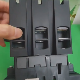
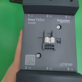
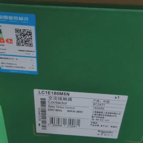
Schneider LC1E180M5N is an موصل التيار المتردد belonging to the TeSys E series, primarily designed for controlling electrical loads such as motors.
المعلومات الأساسية
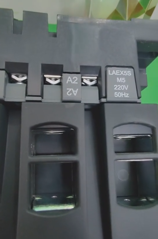
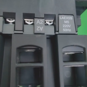
تفسير النموذج: LC1 designates a contactor; E represents the TeSys E series; 180 indicates the rated current; M means the control coil voltage is 220V AC; 5 denotes the coil frequency of 50Hz; N signifies that the product complies with Chinese standards.
ماركة: شنايدر
رقم القطب: 3ص
جهات الاتصال الرئيسية: 3لا (Three Normally Open)
المعلمات التقنية
Rated Operational Current: 18أ (AC-3 duty category)
تصنيف الجهد التشغيلي: ≤690V AC (50/60هرتز)
التحكم في جهد الملف: 220الخامس و
Coil Frequency: 50هرتز
الحياة الكهربائية: Long electrical life under AC-3 duty category
الحياة الميكانيكية: Up to 10 مليون عملية
طريقة التركيب: Supports DIN rail mounting and base plate mounting
فئة الحماية: IP20, preventing direct finger contact
ميزات المنتج
Long Service Life: Boasts a mechanical life of up to 10 million operations and a high electrical life, reducing replacement frequency.
Strong Adaptability: Treated with “TH” حماية, enabling operation in humid and hot environments.
Wide Voltage Tolerance: The coil control voltage can fluctuate within the range of 85%-110% Uc without affecting the product’s normal operation.
High Versatility: Equipped with a universal coil compatible with 50Hz-60Hz frequencies.
تصميم وحدات: Auxiliary contact blocks, on-delay/off-delay contact blocks, mechanical interlocks and other modules can be attached to the main unit. It can also be easily assembled into reversible contactors and star-delta starters.
مجالات التطبيق
Suitable for AC loads with a power factor of ≥0.95. It can be used to make and break normally-started squirrel-cage motors, as well as control electrical loads such as factory equipment, electric heaters, machine tools and various power units.
Installation Guide for Schneider LC1E180M5N Contactor
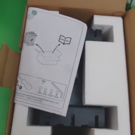
- التحضير قبل التثبيت
- Check Product Specifications
التحقق من النموذج: LC1E180M5N (TeSys E series, rated current 180A, coil voltage 220V AC, 50هرتز)
Inspect the appearance for no damage and ensure the arc chute is intact
Confirm the environment is dry, well-ventilated, free of corrosive gases, with an ambient temperature range of -5℃~+40℃
- Prepare Tools and Materials
Insulated tools (voltage tester, insulated gloves)
المفكات (matching terminal screws)
Torque wrench (recommended torque range: 4-6ن · م)
Cables (main circuit: 10-50مم²; control circuit: 1-2.5مم²)
Cable terminals
Mounting rail (35mm DIN standard) or mounting plate
- احتياطات السلامة
DANGER! Risk of electric shock, explosion or arc flash
All power supplies must be disconnected, locked and tagged in accordance with the LOTO (Lockout/Tagout) procedure before installation, wiring or commissioning
– Verify the absence of voltage with a voltage detection device before operation; never rely solely on instrument displays
– Installation operations shall only be performed by qualified electrical personnel
– Wear appropriate PPE (Personal Protective Equipment) including insulated gloves and safety goggles
– Do not open the arc chute or touch live parts while the contactor is in operation
ثالثا. خطوات التثبيت
- Contactor Fixing
تركيب السكك الحديدية DIN:
- Align the rail clips on the back of the contactor with the 35mm DIN rail
- Press down firmly until a “انقر” يسمع الصوت, indicating the contactor is locked in place
- لإزالة, gently pry the clips with a screwdriver to release the contactor
Base Plate Mounting:
- Secure the contactor using 4 M6 screws through the mounting holes at the bottom of the unit
- Ensure the mounting surface is flat and the contactor is installed vertically (tilt angle <5°) to facilitate heat dissipation
- أسلاك الدائرة الرئيسية (Three-phase System)
| وضع العلامات الطرفية | Connection Content | وصف |
| L1/L2/L3 | Three-phase power supply input | Connect to the output terminal of the circuit breaker or fuse |
| T1/T2/T3 | Load output (e.g. محرك) | Connect to the motor or other electrical loads |
Operation Steps:
- Strip the cable insulation layer to a length of approximately 10-15mm
- Install appropriate cable terminals and crimp them securely
- Insert the cable terminals into the corresponding terminal holes and tighten the screws to the specified torque (4-6ن · م)
- It is recommended to use phase barriers to enhance phase-to-phase insulation, especially for high-current applications
- أسلاك دائرة التحكم
| وضع العلامات الطرفية | Connection Content | وصف |
| أ1 | Control power supply live wire (ل) | Connect to the start signal of the control circuit |
| A2 | Control power supply neutral wire (ن) | Connect to the common terminal of the control circuit |
| جهات الاتصال المساعدة (13-14/21-22) | Signal feedback or interlocking | خياري, used for status indication or interlock control |
Typical Control Circuit Connection (Self-locking Control):
- Control power supply → Stop button (مغلقة عادة) → Start button (مفتوحة عادة) → Contactor terminal A1
- Terminal A2 → Control power supply neutral wire
- Connect the auxiliary normally open contact of the contactor in parallel with the start button (to achieve self-locking)
- تركيب الملحقات (خياري)
Auxiliary Contact Blocks (e.g. LAEN series):
Clip the module onto the side of the contactor until a “انقر” يسمع الصوت, indicating proper installation
Overload Relay (LR E series is recommended):
Mount directly below the contactor and secure with clips; the connection wires are pre-wired internally
- Commissioning and Testing
- Wiring Inspection
Confirm all connections are tight, with no looseness or short circuits
Check that the terminal screw torque meets the requirements
Verify the phase sequence is correct (L1-L2-L3 corresponding to motor rotation direction)
- No-load Test (Without connecting the load)
Turn on the control power supply and test the contactor’s closing and opening actions
Observe if the coil overheats or produces abnormal noise
Check if the auxiliary contacts operate correctly (measure with a multimeter if necessary)
- Load Test
Ensure the main circuit power supply is disconnected and perform an inching test first
Gradually increase the load and monitor the contactor’s temperature rise (لا يتجاوز 60 ألف) and operating noise
Test the overload protection function (if an LR E relay is installed)
- Maintenance Recommendations
التفتيش المنتظم (once a month):
Check if terminal connections are loose (especially in vibrating environments)
Inspect contact wear condition (if contact wear indicators are available)
Check if the arc chute is damaged
Monitor for abnormal operating temperatures
التنظيف والصيانة:
Disconnect the power supply before cleaning dust; do not use solvents to clean internal circuits
Ensure ventilation channels are unobstructed
- استكشاف الأخطاء وإصلاحها
| Problem | الأسباب المحتملة | الحلول |
| Contactor fails to close | No voltage/insufficient voltage at the coil | Check the control power supply and circuit connections |
| Coil damage | Replace the contactor | |
| Excessive operating noise | Contaminated/oxidized iron core contact surfaces | Clean the iron core contact surfaces |
| Unstable power supply voltage | Check power supply quality | |
| Overheating of contacts | Poor contact | Retighten the terminals (pay attention to the specified torque) |
| Excessive load current | Check if the load exceeds the rated value |
سابعا. ملخص
The key to the correct installation of the LC1E180M5N contactor lies in: safe power-off, proper fixing, secure wiring and comprehensive testing. Following this guide not only ensures the reliable operation of the equipment but also extends its service life. بعد التثبيت, please keep the product label and installation records for future maintenance and inspection.
ملحوظة: This guide applies to the Schneider LC1E180M5N contactor and other models in the same series (LC1E120-LC1E630).


")


NH42-63-318x560.png "مفاتيح النقل التلقائي من نوع الكمبيوتر الشخصي CHINT (المنشطات الأمفيتامينية)NH42-63/4SZ")

")

