
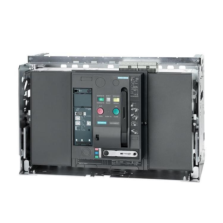


1.انهيار النموذج المتعمق (3WT2M40 ETU35WT F-4P)
| الجزء النموذجي | وصف | شرح مفصل |
| 3وزن | سلسلة المنتجات | قاطع الدائرة الهوائية من سلسلة Siemens SENTRON, التيار المقنن يتراوح من 400A إلى 4000A, قدرة كسر تصل إلى 66 كيلو أمبير |
| 2 | مواصفات الحجم | مقاس 2, النطاق الحالي المقدر من 1000A إلى 2000A |
| م40 | التصنيف الحالي | يشير M40 إلى التيار المقدر In = 1600A (M40 يتوافق مع 1600A, M32 = 1250A, M50 = 2000A) |
| ETU35WT | وحدة الرحلات الإلكترونية | وحدة رحلة الحماية الأساسية ثلاثية المراحل (إل إس آي), مجهزة بشاشة LCD صينية قياسية, توفير تأخير التحميل الزائد لفترة طويلة, ماس كهربائى تأخير وقت قصير ووظائف حماية ماس كهربائى لحظية |
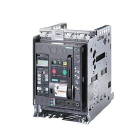
| ف | نوع التركيب | F = التركيب الثابت (W = التركيب القابل للسحب/السحب) |
| 4ص | رقم القطب | أربعة القطب (3P = ثلاثة أقطاب), مناسبة لأنظمة الأسلاك ثلاثية الطور التي تتطلب حماية محايدة |
- جدول المعلمات التقنية الأساسية
2.1 المعلمات الكهربائية الأساسية
| المعلمة | قيمة | معيار |
| تصنيف الجهد التشغيلي (إي) | 500فولت/690 فولت تيار متردد 50/60 هرتز | اللجنة الانتخابية المستقلة 60947-2 |
| التصنيف الحالي (في) | 1600أ | اللجنة الانتخابية المستقلة 60947-2 |
| تصنيف قدرة كسر ماس كهربائى (وحدة العناية المركزة) | 66ال (500V) / 55ال (690V) | اللجنة الانتخابية المستقلة 60947-2 |
| تصنيف وقت قصير الصمود الحالي (اي سي دبليو) | 66كا / 1 ثانية (500V) | اللجنة الانتخابية المستقلة 60947-2 |
| تصنيف الجهد العزل (واجهة المستخدم) | 1000الخامس و | اللجنة الانتخابية المستقلة 60947-2 |
| تردد التشغيل المقدر | 50/60هرتز | اللجنة الانتخابية المستقلة 60947-2 |
| رقم القطب | 4-القطب (3 أقطاب + القطب المحايد) | اللجنة الانتخابية المستقلة 60947-2 |
| نوع التركيب | مُثَبَّت | اللجنة الانتخابية المستقلة 60947-2 |
2.2 معلمات حماية وحدة الرحلة ETU35WT
| وظيفة الحماية | نطاق الإعداد | خاصية الوقت | وصف الوظيفة |
| الزائد تأخير لفترة طويلة (لتر/لتر) | و = 0.4 ~ 1.0 × بوصة (640أ ~ 1600 أ) | الفارق الزمني العكسي, متوافق مع IEC 60947-2 معيار, خاصية I²t القابلة للتكوين | منع المحركات والكابلات من ارتفاع درجة الحرارة والحرق بسبب الحمل الزائد على المدى الطويل |
| ماس كهربائى تأخير قصير الوقت (ست/س) | ISD = 1.5~10×Ir, الافتراضي 3 × إير | فارق زمني محدد, قابل للتعديل من 0.1 ثانية إلى 0.5 ثانية | تحقيق الحماية الانتقائية, عزل مناطق الخطأ, وتجنب انقطاع التيار الكهربائي الشامل للنظام |
| ماس كهربائى لحظية (إنست/أنا) | الثاني = 5 ~ 15 × بوصة, الافتراضي 10×إن | لا تأخير الوقت, وقت التشغيل ≥ 0.02 ثانية | قم بقطع أخطاء الدائرة القصيرة الشديدة بسرعة لحماية المعدات من تأثير التيار الزائد |
| إشارة الرحلة | ميكانيكية + إشارة إلكترونية مزدوجة | – | عرض أسباب الرحلة بشكل حدسي (الزائد / ماس كهربائى / لحظية) |
| وظيفة الذاكرة | تخزين سبب الرحلة ≥ 2 أيام (رحلة بعد التنشيط ≥ 20 دقائق) | – | تسهيل تحليل الأخطاء واستكشاف الأخطاء وإصلاحها |
2.3 المعلمات الميكانيكية والبيئية
| المعلمة | قيمة |
| عمر الخدمة الميكانيكية | ≥ 10,000 العمليات (عملية عدم التحميل) |
| عمر الخدمة الكهربائية | ≥ 1,000 العمليات (في التصنيف الحالي) |
| آلية التشغيل | نوع الشحن الربيعي اليدوي, مع أزرار الإغلاق/الانطلاق |
| فئة الحماية | IP30 (عند تركيبها داخل الخزانة) |
| درجة حرارة التشغيل | -5درجة مئوية~+40 درجة مئوية (لا ديراتينغ), -25درجة مئوية~+55 درجة مئوية (التخفيض مطلوب) |
| الرطوبة النسبية | 5%~95% (غير التكثيف) |
| ارتفاع | ≥ 2000 م (لا ديراتينغ), التخفيض المطلوب ل > 2000م |
| وزن | حوالي 45 كجم (نوع ثابت 4P) |
- مبدأ العمل وآلية الحماية
3.1 مبدأ العمل الأساسي
- عملية عادية: عندما يكون قاطع الدائرة مغلقا, جهات الاتصال الرئيسية تربط الدائرة, يتدفق التيار عبر الدائرة الرئيسية ودائرة أخذ عينات وحدة الرحلة, ويقوم ETU35WT بمراقبة التيار ثلاثي الطور في الوقت الفعلي.
- كشف الخطأ: عندما يتجاوز التيار القيمة المحددة, يحسب ETU35WT وقت الرحلة وفقًا لمنحنى خصائص الحماية.
- عمل الرحلة: عند استيفاء شرط الرحلة, يرسل ETU35WT إشارة رحلة لتشغيل آلية التعثر الكهرومغناطيسي للتشغيل وفتح جهات الاتصال الرئيسية بسرعة.
- عملية إطفاء القوس: يتم إطفاء القوس الناتج عند فتح نقاط الاتصال الرئيسية بسرعة بواسطة غرفة إطفاء القوس, منع إعادة إشعال القوس الكهربائي وقصر الدائرة من مرحلة إلى مرحلة.
3.2 شرح تفصيلي لوظائف الحماية ثلاثية المراحل (ETU35WT LSI)
3.2.1 الزائد حماية التأخير لفترة طويلة (لتر/لتر)
مبدأ: استنادا إلى خاصية الفارق الزمني العكسي (مبدأ تراكم الحرارة), the higher the current, the shorter the trip time (following the I²t law)
Application: Protect cables and motors from long-term overload damage, and withstand short-term overcurrent during motor startup
Setting: و = 0.4 ~ 1.0 × بوصة, usually set to the rated current of the protected equipment
3.2.2 Short-circuit Short-time Delay Protection (ست/س)
مبدأ: Definite time-lag characteristic, set a fixed trip time (0.1s~0.5s) to achieve selective protection
Application: Remain closed before the lower-level circuit breaker operates, only cut off the fault branch, and improve power supply continuity
Setting: ISD = 1.5~10×Ir, usually set to 5~8×Ir, with the time coordinated with the lower-level circuit breaker
3.2.3 Instantaneous Short-circuit Protection (إنست/أنا)
مبدأ: No time-lag characteristic, trip immediately when the current exceeds the set value (≤ 0.02s)
Application: قم بحماية قاطع الدائرة الكهربائية نفسه ومعدات المستوى العلوي من التلف الناتج عن تيار الدائرة القصيرة الضخم (عادة ≥ 10 × بوصة)
Setting: الثاني = 5 ~ 15 × بوصة, يتم ضبطه عادةً على 10 ~ 12 × In لتجنب ذروة التيار أثناء بدء تشغيل المحرك
3.3 أهمية خاصة للحماية ذات 4 أقطاب
مناسب لأنظمة TN-S وTN-C-S, توفير حماية التيار الزائد للخط المحايد (خط ن)
عند حدوث عدم توازن ثلاثي الطور أو خطأ أرضي أحادي الطور, قد يصل تيار الخط المحايد إلى مستوى المرحلة الحالية, والتصميم ذو الأربعة أقطاب يمكن أن يقطع تيار العطل بشكل فعال
الامتثال لمتطلبات الحماية للجنة الانتخابية المستقلة 60364 معيار لأنظمة أربع أسلاك ثلاثية الطور
- دليل التثبيت والأسلاك
4.1 إعداد التثبيت
- متطلبات السلامة: يجب قطع مصدر الطاقة وقفله قبل التثبيت لمنع حدوث صدمة كهربائية
- متطلبات مجلس الوزراء: حجز مساحة التثبيت الكافية (العرض × العمق × الارتفاع: حوالي 600 مم × 800 مم × 1000 مم)
- طريقة التثبيت: قم بالتثبيت على شعاع تثبيت خزانة التوزيع بمسامير M12, عزم الدوران 70 نيوتن متر
4.2 أسلاك الدائرة الرئيسية (4ص)
| صالة | غاية | مواصفات الكابل | عزم الدوران |
| L1/L2/L3 | مدخلات الطاقة على ثلاث مراحل | 4×(120مم² ~ 185 مم²) كابل النحاس | 120ن · م |
| ن | إدخال خط محايد | 120مم²~185 مم² كابل نحاسي | 120ن · م |
| T1/T2/T3 | إخراج الحمل على ثلاث مراحل | 4×(120مم² ~ 185 مم²) كابل النحاس | 120ن · م |
| تينيسي | إخراج خط محايد | 120مم²~185 مم² كابل نحاسي | 120ن · م |
4.3 أسلاك دائرة التحكم
مصدر الطاقة المساعد: التيار المتناوب/تيار مستمر 220 فولت (مصدر طاقة التشغيل لـ ETU35WT)
جهات الاتصال المساعدة: 2 مجموعات مفتوحة عادة (لا) + 2 مجموعات مغلقة عادة (نورث كارولاينا), التيار المقدر 5A/250V AC
إشارة الرحلة: اتصال مغلق عادة (فتح عندما تعثرت) للتنبيه عن بعد
أزرار التحكم: زر الإغلاق (أخضر), زر التعثر (أحمر), يجب أن تكون متصلاً بمصدر طاقة التحكم 24 فولت تيار مستمر أو 220 فولت تيار متردد
- خطوات إعداد وحدة الرحلة ETU35WT
- أدخل وضع الإعداد: اضغط على “Setting” الموجود على لوحة ETU وأدخل كلمة المرور (تقصير 0000)
- الزائد تأخير لفترة طويلة (و): اضبط على التيار المقنن للمعدات المحمية (على سبيل المثال, إذا كان المحرك في = 1600A, تعيين الأشعة تحت الحمراء = 1600A)
- ماس كهربائى تأخير قصير الوقت (ISD): اضبط على 5~8×Ir (على سبيل المثال, ISD = 8×1600 = 12800A), الوقت 0.2 ثانية
- ماس كهربائى لحظية (ثانيا): اضبط على 10 ~ 12 × بوصة (على سبيل المثال, الثاني = 10×1600 = 16000A)
- حفظ المعلمات: اضغط على “يتأكد” زر للحفظ, سوف يخرج ETU تلقائيًا من وضع الإعداد
- اختبار الوظيفة: قم بإجراء اختبارات محاكاة للحمل الزائد والدائرة القصيرة للتحقق من صحة إجراء الرحلة
- دليل تشخيص الأعطال والصيانة
6.1 جدول استكشاف أخطاء الأخطاء الشائعة وإصلاحها
| ظاهرة الخلل | الأسباب المحتملة | الحلول |
| غير قادر على الإغلاق | 1. وحدة رحلة الجهد المنخفض غير مدعومة | 1. تحقق من مصدر طاقة التحكم |
| 2. فشل وحدة الرحلة | 2. استبدل ETU35WT | |
| 3. لم يتم تحرير التعشيق الميكانيكي | 3. حرر جهاز التعشيق | |
| رحلة غير مقصودة | 1. الإعداد الحالي صغير جدًا | 1. إعادة تعيين معلمات الحماية |
| 2. ثلاث مراحل عدم الاتزان الحالي | 2. تحقق من توازن الحمل | |
| 3. ارتفاع درجة الحرارة المحيطة بشكل مفرط | 3. تحسين التهوية وتبديد الحرارة | |
| لا رحلة أثناء التحميل الزائد | 1. الإعداد الحالي كبير جدًا | 1. اضبط Ir على القيمة المناسبة |
| 2. فشل دائرة أخذ العينات ETU | 2. تحقق من المحول الحالي | |
| 3. تشويش آلية التعثر | 3. تنظيف وتشحيم الآلية | |
| لا رحلة خلال ماس كهربائى | 1. قيمة الإعداد الفوري كبيرة جدًا | 1. قم بتقليل قيمة الإعداد Ii |
| 2. فشل وحدة الرحلة الكهرومغناطيسية | 2. استبدل ملف وحدة الرحلة | |
| 3. قوس إطفاء الضرر الغرفة | 3. استبدل غرفة إطفاء القوس |
6.2 دورة الصيانة والمحتوى
| دورة الصيانة | محتوى الصيانة | نقاط التشغيل |
| شهريا | التفتيش البصري | تحقق من وجود علامات ارتفاع درجة الحرارة, اتصالات فضفاضة وضوضاء غير طبيعية |
| ربع سنوية | التنظيف والصيانة | قم بتنظيف غرفة إطفاء القوس ونقاط الاتصال بالهواء المضغوط الجاف بعد انقطاع التيار الكهربائي |
| سنويا | اختبار الوظيفة | قم بإجراء اختبارات محاكاة للحمل الزائد والدائرة القصيرة للتحقق من وظائف الحماية |
| كل 2 سنين | التفتيش الميكانيكي | تحقق من آلية التشغيل وارتداء الاتصال, استبدال إذا لزم الأمر |
| كل 5 سنين | إصلاح شامل | استبدل المكونات القديمة وأعد معايرة معلمات وحدة الرحلة |
- سيناريوهات الاختيار والتطبيق
7.1 السيناريوهات القابلة للتطبيق
- النباتات الصناعية: أنظمة توزيع الطاقة ثلاثية الطور بأربعة أسلاك تتطلب حماية خط محايد
- مراكز البيانات: إمدادات الطاقة للأحمال الحرجة, تتطلب موثوقية عالية وحماية انتقائية
- المباني التجارية: إمداد الطاقة للمعدات الكبيرة مثل المكيفات المركزية ومضخات المياه
- مجال الطاقة الجديد: حماية جانب الإخراج للعاكسات الكهروضوئية وأنظمة تخزين الطاقة
7.2 نقاط الاختيار
- التصنيف الحالي: اختر وفقًا لتيار الحمل المحسوب (في ≥ 1.25 × تيار الحمل المحسوب)
- كسر القدرة: اختر وفقًا لتيار الدائرة القصيرة للنظام (Icu ≥ الحد الأقصى لتيار الدائرة القصيرة للنظام)
- اختيار رقم القطب: حدد 3P للأنظمة ثلاثية الأسلاك ثلاثية الطور, 4P لأنظمة ثلاثية الطور بأربعة أسلاك
- نوع التركيب: حدد F للتركيب الثابت, حدد دبليو (قابل للسحب) لمتطلبات الصيانة عبر الإنترنت
- اختيار وحدة الرحلة:
حدد ETU35WT (إل إس آي) للحماية الأساسية
حدد ETU37WT (إل إس آي جي) لمتطلبات الحماية من الأخطاء الأرضية
حدد ETU45WT (مع وظيفة الاتصال) للتطبيقات المتقدمة
- الملحقات الموصى بها ومعلومات الطلب
| اسم الملحق | نموذج | وصف الوظيفة |
| الاتصال المساعد | LZN102 | يضيف 2 عادة مفتوحة و 2 اتصالات مغلقة عادة للتحكم عن بعد |
| وحدة رحلة الجهد المنخفض | LZN201 | رحلة تلقائيًا عند حدوث فقدان الجهد لحماية سلامة المعدات |
| وحدة رحلة التحويلة | LZN301 | التحكم في الرحلة عن بعد للإغلاق في حالات الطوارئ |
| إغلاق الملف | LZN401 | جهاز إغلاق كهربائي, مناسبة لأنظمة التشغيل الآلي |
| وحدة الاتصالات | كوم16 | اتصال Modbus RTU للمراقبة عن بعد |
نموذج الطلب: 3WT2M40 ETU35WT F-4P
النموذج البديل: النسخة القابلة للسحب 3WT2M40 ETU35WT W-4P
يرث قاطع الدائرة الهوائية من سلسلة Siemens SENTRON 3WT تكنولوجيا التصنيع الألمانية, يوفر حلول موثوقة لحماية توزيع الطاقة, يستخدم على نطاق واسع في مختلف المجالات الصناعية والتجارية, وهو خيار مثالي لضمان استمرارية إمداد الطاقة وسلامة المعدات.


")


NH42-63-318x560.png "مفاتيح النقل التلقائي من نوع الكمبيوتر الشخصي CHINT (المنشطات الأمفيتامينية)NH42-63/4SZ")

")

