
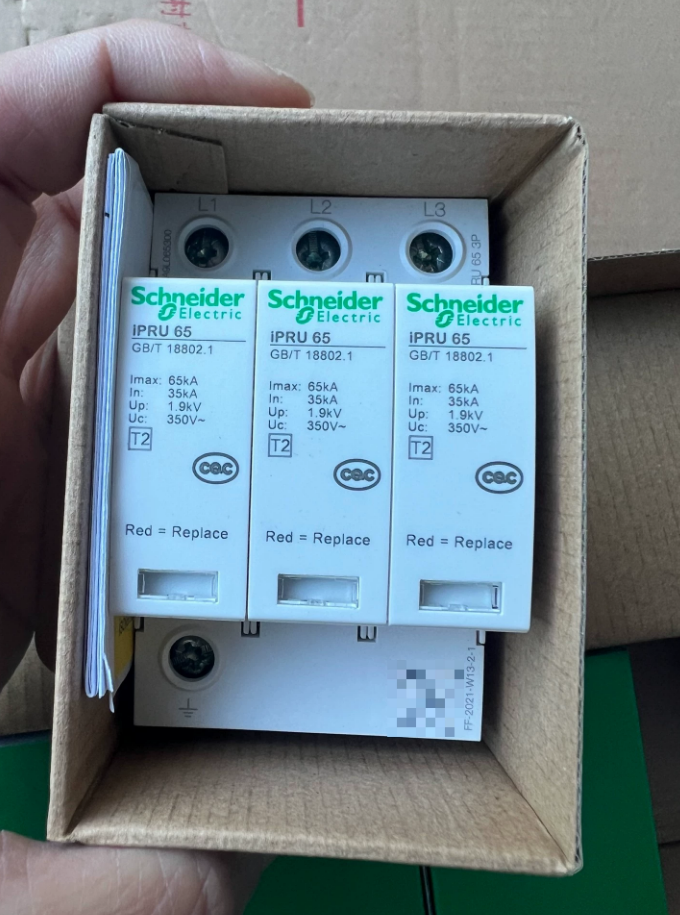

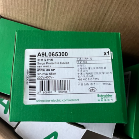
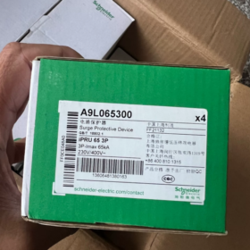
Electricidad Schneider A9L065300 (IPRU 65-3P) es un dispositivo de protección contra sobretensiones enchufable tipo II (SPD), Especialmente diseñado para sistemas de distribución de energía trifásicos de tres hilos.. Con una corriente de descarga máxima de 65kA y un voltaje de funcionamiento continuo de 350V, Es adecuado para protección contra sobretensiones en sistemas de distribución de energía industriales y comerciales..
Parámetros técnicos básicos
| Elemento de parámetro | Valor | Observaciones |
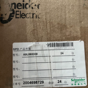
| Modelo | A9L065300 (IPRU 65-3P) | 3-versión de poste sin señalización remota |
| Tipo de protector | Tipo II (IEC 61643-11/ES 18802.1) | Protección secundaria contra sobretensiones para sistemas de distribución de energía. |
| Tecnología de protección | MOVIMIENTO (Varistor de óxido metálico) | Protección de modo común (L-PE) |
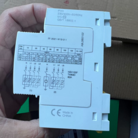
| Tensión de funcionamiento nominal Ue | 230/400V CA 50/60 Hz | Adecuado para sistemas trifásicos de tres hilos. |
| Tensión máxima de funcionamiento continuo Uc | 350V (L-PE) | Nivel de tensión de protección en modo común |
| Corriente de descarga nominal en | 35el (8/20μs) | Capacidad de resistencia a la sobretensión |
| Corriente máxima de descarga Imax | 65el (8/20μs) | Capacidad máxima de derivación de corriente de sobretensión |
| Nivel de protección de voltaje elevado | <1,5kV (L-PE) | Limita la sobretensión a un rango seguro |
| Tiempo de respuesta | ≤25 ns | Supresión rápida de sobretensión transitoria |
| Conteo de polos | 3PAG | Sistema trifásico de tres hilos. (sin protección de cable neutro) |
| Sistema de puesta a tierra | TN-C | Adecuado para sistema de puesta a tierra trifásico de tres hilos. |
| Método de montaje | Carril DIN (35milímetros) | Instalación de gabinete de distribución estándar |
| Dimensiones (Alto×Ancho×Profundidad) | 85mm×54mm×64mm | Diseño compacto, ahorra espacio en el gabinete |
| Capacidad de cableado | Cable macizo 2,5–35 mm², Cable flexible de 2,5 a 25 mm² | Terminales tipo túnel, Soporta cableado superior e inferior. |
| Cable recomendado | Cable L 4mm², Cable PE 6mm² | Garantiza la conductividad y el rendimiento de disipación de calor. |
| Par de apriete | 3.5Nuevo Méjico | Especificación de conexión de terminales, evita que se afloje |
| Grado de protección | Panel frontal IP40, Terminales IP20 | A prueba de polvo y humedad, protección segura |
| Temperatura de funcionamiento | −25°C a +60°C | Se adapta a las fluctuaciones de temperatura en entornos industriales. |
| Período de garantía | 18 meses | Garantía de calidad y rendimiento del producto. |
Características funcionales
- Diseño enchufable: La estructura modular admite el intercambio en caliente de módulos de protección en línea sin cortes de energía, Mejorar la eficiencia del mantenimiento y la continuidad del suministro de energía..
- Indicación de estado: ventana mecanica (blanco/rojo) Muestra intuitivamente el estado de funcionamiento: el blanco indica funcionamiento normal., El rojo indica que es necesario reemplazar el módulo., Facilitar la inspección y la alerta temprana de fallos..
- Seguridad y confiabilidad: Cumple con los estándares medioambientales RoHS/REACH, adopta tecnología sin plomo, adecuado para sistema de puesta a tierra TN-C, Garantizar la seguridad del personal y del equipo..
- Fuerte adaptabilidad: Compatible con instalación en carril DIN estándar, El tamaño compacto se adapta a la mayoría de los gabinetes de distribución., admite cableado superior e inferior con conexión flexible.
Puntos de instalación y mantenimiento
- Especificaciones de instalación
Instalar en el lado entrante del gabinete de distribución., y conecte un disyuntor o fusible de 10 a 16 A en serie en el extremo frontal para evitar la propagación de fallas por cortocircuito.
Siga estrictamente el cableado correspondiente de L1, L2 y L3, garantizar una conexión confiable del cable PE, con resistencia de puesta a tierra ≤4Ω.
Minimizar la longitud del cable (≤50cm) para reducir el impacto de la impedancia de la línea en el rendimiento de la protección.
- Recomendaciones de mantenimiento
Compruebe periódicamente la ventana de indicación mecánica.; reemplace el módulo inmediatamente si se pone rojo.
Vuelva a probar la resistencia de la conexión a tierra y la estanqueidad de los terminales anualmente para garantizar la eficacia de la protección..
Acortar el ciclo de inspección a una vez por trimestre en áreas propensas a sobretensiones (como zonas de impacto de rayos).
Escenarios de selección y aplicación
Escenarios aplicables: Líneas de producción industriales, distribución de energía para edificios comerciales, front-end de UPS en centros de datos, Circuitos de control de motores trifásicos y otras ocasiones que requieren protección secundaria contra sobretensiones..
Consejos de selección
Para sistemas trifásicos de cuatro hilos. (3P+N), se recomienda seleccionar A9L065600 (IPRU 65-3P+N).
Para función de señalización remota (monitoreo de estado remoto), A9L065401 (IPRU 65r-4P) es opcional, adecuado para sistemas TN-S.
Con alta capacidad de resistencia a sobretensiones, respuesta rápida y mantenimiento conveniente, A9L065300 (IPRU 65-3P) se ha convertido en una solución óptima para la protección secundaria contra sobretensiones en sistemas de distribución de energía trifásicos de tres hilos.. Es ampliamente utilizado en escenarios industriales y comerciales., Proteger eficazmente los equipos eléctricos contra daños por sobretensión transitoria..
La siguiente es la comparación de parámetros., diferencias de selección y sugerencias de reemplazo de los modelos principales de Schneider Electric iPRU 65 Serie (SPD enchufable tipo II), facilitar la adaptación rápida de las necesidades de protección contra sobretensiones para sistemas de distribución de energía trifásicos.
- Tabla de comparación de parámetros de modelos principales en iPRU 65 Serie
| Elemento de parámetro | A9L065300 | A9L065600 | A9L065401 | A9L065402 |
| (IPRU 65-3P) | (IPRU 65-3P+N) | (IPRU 65r-3P+N) | (IPRU 65r-4P) | |
| Nombre completo del modelo | IPRU 65-3P | IPRU 65-3P+N | IPRU 65r-3P+N | IPRU 65r-4P |
| Configuración de polos | 3PAG (Trifásico de tres hilos.) | 3P+N (Trifásico de cuatro hilos.) | 3P+N (Trifásico de cuatro hilos.) | 4PAG (Protección total para trifásicos de cuatro hilos.) |
| Función de señalización remota | Ninguno | Ninguno | Disponible (Monitoreo de estado remoto) | Disponible (Monitoreo de estado remoto) |
| Tipo de protector | Tipo II (CEI 61643-11) | Tipo II (CEI 61643-11) | Tipo II (CEI 61643-11) | Tipo II (CEI 61643-11) |
| Tecnología de protección | MOVIMIENTO (Modo común L-PE) | MOVIMIENTO (Modo común L-PE + Modo diferencial L-N) | MOVIMIENTO (Modo común L-PE + Modo diferencial L-N) | MOVIMIENTO (Modo común L-PE + Modo diferencial L-N) |
| Tensión de funcionamiento nominal Ue | 230/400V CA 50/60 Hz | 230/400V CA 50/60 Hz | 230/400V CA 50/60 Hz | 230/400V CA 50/60 Hz |
| Tensión máxima de funcionamiento continuo Uc | 350V (L-PE) | 350V (M-F/M-N) | 350V (M-F/M-N) | 350V (M-F/M-N) |
| Corriente de descarga nominal en | 35el (8/20μs) | 35el (8/20μs) | 35el (8/20μs) | 35el (8/20μs) |
| Corriente máxima de descarga Imax | 65el (8/20μs) | 65el (8/20μs) | 65el (8/20μs) | 65el (8/20μs) |
| Nivel de protección de voltaje elevado | <1,5kV (L-PE) | <1,5kV (L-PE) | <1,5kV (L-PE) | <1,5kV (L-PE) |
| <2,0 kV (LN) | <2,0 kV (LN) | <2,0 kV (LN) | ||
| Tiempo de respuesta | ≤25 ns | ≤25 ns | ≤25 ns | ≤25 ns |
| Compatibilidad del sistema de puesta a tierra | TN-C | TN-C/TN-S | TN-S/TT | TN-S/TT |
| Método de montaje | Carril DIN (35milímetros) | Carril DIN (35milímetros) | Carril DIN (35milímetros) | Carril DIN (35milímetros) |
| Dimensiones (Alto×Ancho×Profundidad) | 85mm×54mm×64mm | 85mm×86mm×64mm | 85mm×86mm×64mm | 85mm×86mm×64mm |
| Capacidad de cableado | Cable macizo 2,5–35 mm² | Cable macizo 2,5–35 mm² | Cable macizo 2,5–35 mm² | Cable macizo 2,5–35 mm² |
| Cable flexible de 2,5 a 25 mm² | Cable flexible de 2,5 a 25 mm² | Cable flexible de 2,5 a 25 mm² | Cable flexible de 2,5 a 25 mm² | |
| Especificación de cable recomendada | Cable L 4mm² | Cable L 4mm² | Cable L 4mm² | Cable L 4mm² |
| Cable PE 6mm² | Cable N 4mm² | Cable N 4mm² | Cable N 4mm² | |
| Cable PE 6mm² | Cable PE 6mm² | Cable PE 6mm² | ||
| Par de apriete | 3.5Nuevo Méjico | 3.5Nuevo Méjico | 3.5Nuevo Méjico | 3.5Nuevo Méjico |
| Grado de protección | Panel frontal IP40 | Panel frontal IP40 | Panel frontal IP40 | Panel frontal IP40 |
| Terminales IP20 | Terminales IP20 | Terminales IP20 | Terminales IP20 | |
| Rango de temperatura de funcionamiento | −25°C a +60°C | −25°C a +60°C | −25°C a +60°C | −25°C a +60°C |
| Período de garantía | 18 meses | 18 meses | 18 meses | 18 meses |
| Características principales | Trifásico de tres hilos. | Trifásico de cuatro hilos. | Trifásico de cuatro hilos. | Protección total para trifásicos de cuatro hilos. |
| Sin señalización remota | Sin señalización remota | Con señalización remota | Con señalización remota |
- Diferencias de selección y guía de escenarios de aplicación
| Dimensión de selección | Modelo recomendado | Escenario aplicable | Consideraciones clave |
| Tipo de sistema | 3PAG (A9L065300) | Trifásico de tres hilos. (TN-C) sistema | No se requiere protección del cable neutro, Adecuado para sistemas de distribución de energía industriales antiguos. |
| 3P+N (A9L065600/401) | Trifásico de cuatro hilos. (TN-C/TN-S) sistema | Se requiere protección de modo diferencial L-N, Equipos de equilibrio y seguridad de líneas. | |
| 4PAG (A9L065402) | Trifásico de cuatro hilos. (TN-S/TT) sistema | Se requiere protección total para todos los circuitos L1-L2-L3-N-PE | |
| Requisito de monitoreo | Sin señalización remota (A9L065300/600) | Escenarios de protección básicos con inspección manual periódica | Prioridad de costos, adecuado para pequeños edificios comerciales |
| Con señalización remota (tipo r, A9L065401/402) | Carga crítica y escenarios desatendidos | Necesita monitoreo remoto del estado del SPD y vinculación con sistemas de alarma | |
| Nivel de riesgo | IPRU 65 Serie | Zonas de alto riesgo (zonas de impacto de rayos, zonas industriales) | Imáx=65kA, soportando un fuerte impacto de oleada |
| IPRU 40 Serie | Zonas de riesgo medio (distritos comerciales, edificios de oficinas) | Imáx=40kA, protección regular contra sobretensiones | |
| IPRU 20 Serie | Zonas de bajo riesgo (edificios residenciales, equipo de carga ligera) | Imáx=20kA, solución de protección económica |
III. Modelos de reemplazo e instrucciones de compatibilidad
- Reemplazo intraserie
A9L065300 (3PAG) Se puede sustituir por A9L065401. (3P+N con señalización remota) para adaptarse a la actualización del sistema al tipo TN-S.
A9L065600 (3P+N) Se puede sustituir por A9L065402. (4P con señalización remota) para mejorar la integralidad de la protección.
- Reemplazo entre series
El IPRU 65 La serie es funcionalmente compatible con el iPRD 65 Serie (como A9L65601), y la Serie iPRD está más enfocada a la adaptación de sistemas de TI.
Para un mayor nivel de protección (Imáx=80kA), el iPF K 80 Serie (como A9L15586) puede ser considerado.
- Compatibilidad de instalación
Todos los productos de la serie iPRU se instalan en rieles DIN estándar de 35 mm., y no se requiere ninguna modificación de la estructura del gabinete durante el reemplazo.
La señalización remota (tipo r) Los modelos necesitan reservar una interfaz de alimentación de 24 V CC para la transmisión de la señal de estado..
- Puntos complementarios de instalación y mantenimiento
- Protección frontal: Todos los modelos deben conectarse con un disyuntor o fusible de 10 a 16 A en serie para evitar cortocircuitos causados por fallas del SPD..
- Requisitos de cables: La longitud de los cables de conexión debe ser ≤50 cm para reducir el impacto de la impedancia de la línea en el rendimiento de la protección..
- Indicación de estado: La ventana blanca significa funcionamiento normal.; La ventana roja significa falla del módulo y necesita reemplazo..
- Función de señalización remota: Los modelos tipo r proporcionan contactos normalmente abiertos/normalmente cerrados., que se puede conectar a PLC o sistemas de monitoreo para lograr una alerta temprana remota.
El IPRU 65 La serie satisface las necesidades de protección contra sobretensiones de diferentes sistemas de distribución de energía trifásicos a través de un diseño modular enchufable y una configuración de protección graduada.. Durante la selección, Se debe dar prioridad a la coincidencia del tipo de sistema. (3P/3P+N/4P) y requisitos de seguimiento (con o sin señalización remota), y seleccionar la especificación de corriente de descarga adecuada según el nivel de riesgo para garantizar el funcionamiento seguro de los equipos eléctricos..


")


NH42-63-318x560.png "Interruptores de transferencia automática tipo PC CHINT (ATS)NH42-63/4SZ")

")

