 Contacteur,disjoncteur,onduleur solaire,compteur électrique,batteries solaires

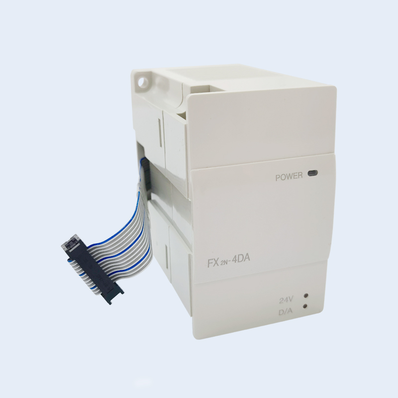


Detailed Explanation of Mitsubishi PLC Analog Expansion Module FX2N-4DA The FX2N-4DA is a 4-channel analog output special function module for Mitsubishi Electric’s MELSEC-F series PLCs. It converts the digital signals inside the PLC into standard analog voltage or current signals to control actuators such as frequency converters, control valves and servo drives. This module has been discontinued, and the FX3U-4DA is recommended as a replacement.
- Core Specification Parameters
| Élément de paramètre | Detailed Specification |
| Channel Configuration | 4 independent analog output channels, each channel can be set with a signal type individually |
| Output Signal Type | • Voltage output: DC -10V ~ +10V (resolution 5mV, load resistance ≥1kΩ) |
| • Current output: DC 0~20mA or 4~20mA (resolution 20μA, load resistance ≤500Ω) | |
| Resolution | Voltage: 11-bit binary + 1 sign bit (corresponding digital value -2000~+2000) |
| Current: 10-bit binary (corresponding digital value 0~1000) | |
| Maximum resolution 12-bit | |
| Conversion Accuracy | Voltage: ±1% of full scale (at 25℃) |
| Current: ±0.5% of full scale (at 25℃) | |
| Conversion Speed | Approximately 10ms per channel (approximately 40ms for simultaneous conversion of all channels) |
| Buffer Memory (BFM) | 32 16-bit registers for parameter setting and data interaction |
| Occupied I/O Points | 8 points (counted as a special function module) |
| Power Supply Requirement | Module power supply: DC 5V, 30mA (provided by PLC expansion power supply) |
| External load power supply: C.C 24 V, maximum. 60mA (facultatif) | |
| Dimensions | 43mm (W) × 98mm (H) × 75mm (D) (standard FX series module size) |
| Environnement opérationnel | Température: 0~55℃, Humidité: 35%~85%RH (pas de condensation) |
- Caractéristiques fonctionnelles
- Channel Independence: Le 4 channels can be set to voltage or current output separately, flexibly adapting to different controlled objects
- Selectable Digital Range: Supports unidirectional (0~10V/0~20mA) and bidirectional (-10V~+10V) output to meet different control requirements
- Gain/Offset Adjustment: Gain and offset calibration can be performed for each channel through BFM registers to improve control accuracy
- Fault Diagnosis: Equipped with open-circuit detection function, and fault status can be read through BFM registers
- Compatibilité: Adaptable to FX1N, FX2N, FX3G, FX3U, FX2NC, FX3GC and FX3UC series PLC hosts
III. Méthode de câblage
- Basic Wiring Principle
Voltage output: Channel positive (V+) connected to load positive, Channel negative (V-) connected to load negative
Current output: Channel positive (I+) connected to load positive, Channel negative (I-) connected to load negative
The common terminal (GND) must be reliably connected to the power ground of the PLC and the load
- 4-20mA Current Output Wiring
Set the I/O switch on the module to the current gear, and set the corresponding digital range in the program (par ex., 4mA corresponds to a digital value of 200, 20mA corresponds to a digital value of 1000)
- Programming Method (Mitsubishi GX Works2/GX Developer)
The FX2N-4DA writes digital values via the TO instruction and reads status information via the FROM instruction, with parameter configuration using the Buffer Memory (BFM).
- Module Address Setting
Special function module number: 0~7 (set according to the module connection order)
BFM addresses occupied by the module: 0~31
- Scénarios d'application
- Process Control: Controls analog parameters such as temperature, pressure and flow, and drives actuators like electric control valves and proportional valves
- Contrôle de mouvement: Provides frequency reference signals for frequency converters to control motor speed; delivers speed or position commands to servo drives
- Continuous Regulation: Achieves precise and continuous control of tension, speed and position in production lines such as packaging, printing and textile manufacturing
- Hybrid System: Cooperates with analog input modules (par ex., FX2N-4AD) to build a complete closed-loop control system
- Alternative Models and Notes
- Modèles alternatifs recommandés
| Original Model | Alternative Model | Main Improvements |
| FX2N-4DA | FX3U-4DA | • Resolution upgraded to 16-bit (digital value 0~32000) |
| • Conversion speed increased to 2.1ms per channel | ||
| • Supports more signal types and calibration functions | ||
| • Maintains basic programming compatibility |
- Notes de remplacement
- Program Modification: The BFM 0 initialization parameters of the FX3U-4DA are different from those of the FX2N-4DA, and the channel mode needs to be reset
- Digital Range: The FX3U-4DA has a larger digital value range (0~32000), and the output value calculation method needs to be adjusted
- Wiring Compatibility: The basic wiring method is the same, but the setting of the I/O switch of the FX3U-4DA must be confirmed
VII. Common Troubleshooting
- No Output Signal:
Check the module power supply and extension cable connection
Confirm that the BFM 0 channel mode is set correctly
Check if the digital value is within the valid range
- Low Output Accuracy:
Perform gain/offset calibration (via BFM 10~17)
Check if the load resistance meets the requirements
Confirm normal communication between the PLC host and the module
- Fault Indicator Light On:
Read the BFM 20 fault status register
Check if the open-circuit detection function is enabled
Confirm the stability of the external power supply
Comparison Table of Mitsubishi FX2N-4DA and 4-Channel Analog Output Modules of Other Brands
The following is a detailed comparison of the FX2N-4DA with the same type of modules from mainstream PLC brands, including Mitsubishi’s own alternative models, corresponding products from international brands (Siemens, Omron, Schneider) and domestic brands (Xinje, Innovation), for reference in model selection, replacement and system integration.
- Mitsubishi’s Own Alternative Models
| Original Model | Recommended Alternative Model | Main Differences and Improvements |
| FX2N-4DA | FX3U-4DA | • Resolution upgraded to 16-bit (digital value 0~32000) |
| • Conversion speed increased to 2.1ms per channel | ||
| • Accuracy improved to ±0.3% of full scale | ||
| • Supports more calibration functions | ||
| • Maintains basic programming compatibility (slight adjustment to BFM register structure) | ||
| FX3U-4DA-ADP | • Compact design, occupying less space | |
| • Suitable for FX3UC series PLCs | ||
| • Basic functions consistent with FX3U-4DA |
- Comparison Table of 4-Channel Analog Output Modules of Mainstream Brands
| Marque | Modèle | Signal Type | Conversion Accuracy | Compatible PLC Series |
| Mitsubishi | FX2N-4DA | Voltage: -10V~+10V/0~10V | Voltage: ±1%FS | FX1N/FX2N/FX3G/FX3U |
| Current: 0~20mA/4~20mA | Current: ±0.5%FS | |||
| Siemens | 6ES7288-3AQ04-0AA0 | Voltage: 0~10V/-10V~+10V | ±0.5%FS | S7-200 SMART |
| (S7-200 SMART SM AQ04) | Current: 0~20mA/4~20mA | |||
| 6ES7232-4HD32-0XB0 | Voltage: 0~10V/-10V~+10V | ±0.3%FS | S7-1200 | |
| (S7-1200 SM 1232) | Current: 0~20mA/4~20mA | |||
| Omron | CP1W-DA042 | Voltage: 0~5V/0~10V/-10V~+10V | Voltage: ±0.3%FS | CP1H/CP1L/CP1E |
| Current: 0~20mA/4~20mA | Current: ±0.3%FS | |||
| CJ1W-DA041 | Voltage: 0~5V/0~10V/-10V~+10V | ±0.2%FS | CJ1 Series | |
| Current: 0~20mA/4~20mA | ||||
| Schneider | TM3AQ4 | Voltage: 0~10V/-10V~+10V | ±0.5%FS | Modicon M221/M241/M251 |
| Current: 0~20mA/4~20mA | ||||
| BMXAMO0410 | Voltage: 0~10V/-10V~+10V | ±0.1%FS | Modicon X80 Series | |
| (Modicon X80 Series) | Current: 0~20mA/4~20mA | |||
| Xinje | XD-E4DA | Voltage: 0~5V/0~10V/-5V~+5V/-10V~+10V | ±0.5%FS | XD Series |
| Current: 0~20mA/4~20mA | ||||
| XC-E4DA | Voltage: 0~5V/0~10V/-10V~+10V | ±0.5%FS | XC Series | |
| Current: 0~20mA/4~20mA | ||||
| Innovation | H1U-4DA | Voltage: 0~5V/0~10V/-10V~+10V | ±0.5%FS | H1U Series |
| Current: 0~20mA/4~20mA |
III. Key Replacement Considerations
- Compatibility Matching
Different brands of PLCs have different expansion bus protocols, making direct physical cross-brand replacement impossible
Lors du remplacement, hardware factors such as PLC host model, number of expansion slots and power supply mode must be considered
In terms of software, the analog output program needs to be rewritten (there are significant differences in the instruction systems of different brands)
- Functional Parameter Comparison
Resolution: The FX2N-4DA is 12-bit (including sign bit), while modern modules are generally upgraded to 14~16-bit
Conversion Speed: Increased from 10ms/channel to 2~5ms/channel, suitable for high-speed control applications
Accuracy Grade: Improved from ±1%FS to ±0.3%~±0.5%FS for more precise control
Diagnostic Functions: Modern modules generally support advanced diagnostics such as open-circuit detection and overcurrent protection
- System Integration Suggestions
To maintain the Mitsubishi PLC system, the FX3U-4DA is the preferred replacement with minimal modifications
For cross-brand replacement, the electrical wiring and control program need to be redesigned
Modules of domestic brands (Xinje, Innovation) have high cost performance and are suitable for model selection in new projects
- Key Points of Replacement Implementation
- Hardware Level
Confirm that the power supply requirements (DC5V/24V) of the new module match the PLC expansion power supply
Reconnect the load circuit, paying attention to signal polarity and common terminal connection
Check if the load resistance meets the requirements of the new module (voltage output ≥1kΩ, current output ≤500Ω)
- Software Level
Reconfigure the channel mode (voltage/current selection)
Adjust the digital value range (par ex., 0~32000 for FX3U-4DA, 0~1000/±2000 for FX2N-4DA)
Modify the TO/FROM instruction parameters to adapt to the BFM register structure of the new module
Add a fault diagnosis program to utilize the advanced diagnostic functions of modern modules


")


")

NH42-63-318x560.png "Commutateurs de transfert automatiques de type PC CHINT (ATS)NH42-63/4SZ")


