 гӮігғігӮҝгӮҜгӮҝ,гӮөгғјгӮӯгғғгғҲгғ–гғ¬гғјгӮ«гғј,гӮҪгғјгғ©гғјгӮӨгғігғҗгғјгӮҝгғј,йӣ»ж°—гғЎгғјгӮҝгғј,еӨӘйҷҪйӣ»жұ

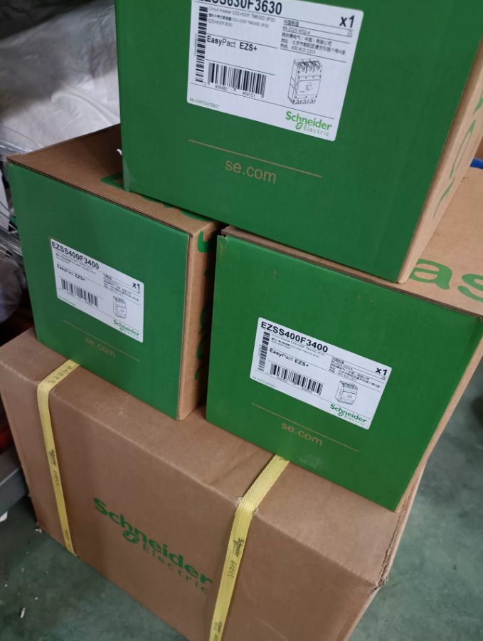

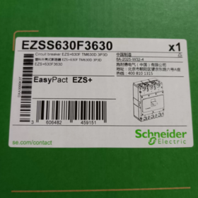
Technical Specifications and Selection Guide for Schneider EZSS630F3630
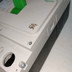
EZSS630F3630 is a 3P 630A Moulded Case Circuit Breaker (MCCB) from Schneider ElectricвҖҷs EasyPact EZS+ Series (Dunhuang Series). Its official order code is EZSS630F3630, with the full model description EZS-S630 36kA TM630D 3P3D, designed for power distribution protection.
- еһӢејҸгӮігғјгғүгҒ®иӘ¬жҳҺ
| гғўгғҮгғ«гӮ»гӮ°гғЎгғігғҲ | иӘ¬жҳҺ |
| EZS | EasyPact EZS+ Series MCCB |
| S | жЁҷжә–гӮҝгӮӨгғ— |
| 630 | Frame current 630A |
| F | йҒ®ж–ӯе®№йҮҸгӮҜгғ©гӮ№, 36гҒ® (415VAC) |
| 3 | 3 жҘө |
| 630 | Rated current 630A |
| TM630D | ThermalвҖ‘magnetic trip unit, rated 630A, DвҖ‘curve |
- гӮігӮўжҠҖиЎ“гғ‘гғ©гғЎгғјгӮҝ
| гӮўгӮӨгғҶгғ | д»•ж§ҳ |
| иЈҪе“ҒгӮҝгӮӨгғ— | Moulded Case Circuit Breaker (MCCB) |
| е®ҡж јйӣ»ең§ | 400/415VAC 50/60Hz |
| е®ҡж јйӣ»жөҒ (гҒ§) | 630гҒӮ |
| гғ•гғ¬гғјгғ йӣ»жөҒ (Iu) | 630гҒӮ |
| жҘөж•° | 3P3D (3вҖ‘pole, 3вҖ‘wire protection) |
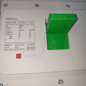
| 究жҘөгҒ®еҲ¶еӢ•иғҪеҠӣ (ICU) | 36гҒ® (415VAC) |
| гӮөгғјгғ“гӮ№гғ–гғ¬гғјгӮӯе®№йҮҸ (пј©пјЈпјі) | 36гҒ® (100% ICU) |
| Trip Unit | ThermalвҖ‘magnetic trip (TMвҖ‘D), with longвҖ‘time overload and instantaneous shortвҖ‘circuit protection |
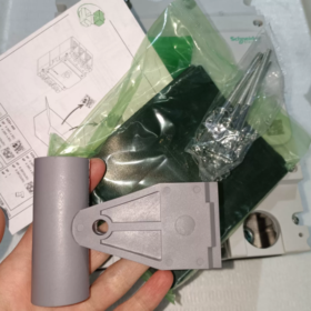
| еҸ–гӮҠд»ҳгҒ‘ | дҝ®зҗҶжёҲгҒҝ (жЁҷжә–), plugвҖ‘in/withdrawable optional (with accessories) |
| з№ӢгҒҢгӮҠ | Front connection (жЁҷжә–), rear/plugвҖ‘in connection optional |
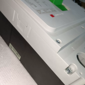
| Ingress Protection | IP30 (device body) |
| Ambient Conditions | Temperature вҖ‘5в„ғ~+40в„ғ, жЁҷй«ҳ вүӨ2000m, жұҡжҹ“еәҰ 2/3 |
| Standards | IEC 60947вҖ‘2, GB 14048.2 |
- Application Environment
- Main Applications
Main or branch switch in low-voltage distribution systems of industrial plants, commercial buildings and large public facilities
Secondary distribution, civil construction and electromechanical markets
Protect motors, еӨүең§еҷЁ, generators and other electrical equipment against overload and short-circuit damage
- з’°еўғиҰҒ件
еӢ•дҪңжё©еәҰ: -5в„ғпҪһ+40в„ғ (derating required above 40в„ғ)
Relative humidity: вүӨ95%, non-condensing
й«ҳеәҰ: вүӨ2000m (derating required above 2000m)
Installation location: Indoor, vertical mounting (inclination вүӨ5В°)
жұҡжҹ“еәҰ: зЁӢеәҰ 2 (жЁҷжә–), applicable to degree 3 environments (with special treatment)
- Cross-Brand Equivalent/Replacement Models
| гғ–гғ©гғігғү | д»Јжӣҝж©ҹзЁ® | еӮҷиҖғ |
| гӮ·гғҘгғҠгӮӨгғҖгғј | CVS630F ETS2.3 630A 3P3D (LV563505) | Upgraded electronic trip unit with LSI protection |
| гӮ·гғҘгғҠгӮӨгғҖгғј | NSX630F Micrologic 2.3 630A 3P3D (LV432876) | HighвҖ‘performance flagship model, full electronic protection, communication optional |
| ABB | Tmax T6N630 TMD 630/3P | Equivalent thermalвҖ‘magnetic MCCB |
| гӮ·гғјгғЎгғігӮ№ | 3VA6300вҖ‘6EL32вҖ‘0AA0 | 630A 3P 36kA thermalвҖ‘magnetic MCCB |
| гғҒгғігғҲ | NM1вҖ‘630S/3300 630A | еӣҪеҶ…д»Јжӣҝе“Ғ, 36kAйҒ®ж–ӯе®№йҮҸ |
- Official Order Information
жӯЈејҸжіЁж–ҮгӮігғјгғү: EZSS630F3630
Common Accessories:
иЈңеҠ©жҺҘзӮ№: LV429310 (1NO+1NC)
Shunt trip: LV429410 (220VAC)
Undervoltage release: LV429510 (220VAC)
Plug-in base: LV429100 (for 630A)
Motor mechanism: LV420089 (24VDC)
- гҒ“гҒ®гӮ·гғӘгғјгӮәгҒ®е…ЁгғўгғҮгғ«гғӘгӮ№гғҲ (630A Frame)
| гғўгғҮгғ« | йҒ®ж–ӯе®№йҮҸ | жҘө | е®ҡж јйӣ»жөҒ | Trip Unit |
| EZSS630E3630 | 25гҒ® | 3P | 630гҒӮ | TMвҖ‘D |
| EZSS630F3630 | 36гҒ® | 3P | 630гҒӮ | TMвҖ‘D |
| EZSS630N3630 | 50гҒ® | 3P | 630гҒӮ | TMвҖ‘D |
| EZSS630H3630 | 70гҒ® | 3P | 630гҒӮ | TMвҖ‘D |
| EZSS630F4630 | 36гҒ® | 4P | 630гҒӮ | TMвҖ‘D |
- Installation and Maintenance Notes
- иЁӯзҪ®дёҠгҒ®жіЁж„ҸдәӢй …
For fixed mounting, reserve sufficient operating space (handle space вүҘ120mm)
Tighten terminals to specified torque (recommended for copper conductors: 40NВ·m for M10 bolts)
Maintain spacing вүҘ20mm between side-by-side units for proper heat dissipation
- гғЎгғігғҶгғҠгғігӮ№гҒ«й–ўгҒҷгӮӢжҺЁеҘЁдәӢй …
Regular inspection (at least once per year): еӨ–иҰі, fasteners, operating mechanism flexibility
After short-circuit tripping, inspect contact condition and replace if necessary
Thermal-magnetic trip units are non-adjustable; replace with electronic trip models if parameter adjustment is needed
- Selection and Replacement Recommendations
- Selection Factors
System short-circuit current level (ensure Icu вүҘ calculated value)
Load type (D-curve for distribution protection, motor-specific type for motor protection)
Installation space and operation method
Future expansion (reserve 10%вҖ“20% margin)
- д»ЈжӣҝгӮҪгғӘгғҘгғјгӮ·гғ§гғі
For more precise protection and adjustable parameters, upgrade to CVS630F ETS2.3 electronic trip model
For communication and remote monitoring, select NSX630F series with intelligent trip units such as Micrologic 5.3A
For budget-limited projects, consider domestic alternatives including Chint NM1 and Delixi CDM3 series
Detailed Connection Methods for Schneider EZSS630F3630
The standard connection method of Schneider EZSS630F3630 (EZS-S630 36kA TM630D 3P3D) is fixed front connection, with multiple optional connection configurations as follows:
- Basic Connection Methods and Configuration Options
| Mounting Type | Connection Direction | Supported | еӮҷиҖғ |
| дҝ®зҗҶжёҲгҒҝ (жЁҷжә–) | Front connection | вң“ Standard | Main circuit cables/busbars connected from front, easy operation, good heat dissipation |
| дҝ®зҗҶжёҲгҒҝ | Rear connection | вң“ Optional | Special configuration required, suitable for compact panel space |
| PlugвҖ‘in (гӮӘгғ—гӮ·гғ§гғі) | Front connection | вң“ Optional | Requires plugвҖ‘in base (дҫӢгҒҲгҒ°. LV429100) for quick replacement and maintenance |
| PlugвҖ‘in | Rear connection | вң— Not supported | PlugвҖ‘in rear connection not available for EZS+ 630A |
| Withdrawable | Any direction | вң— Not supported | Withdrawable mounting not available for EZS+ series |
- Connection Technical Details
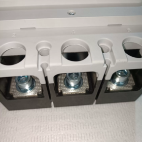
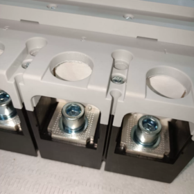
- Terminal Types
дё»еӣһи·Ҝ: Copper bolt terminals, suitable for cables or busbars
еҲ¶еҫЎеӣһи·Ҝ (with auxiliary contacts, shunt/undervoltage releases): Plug-in terminals for easy secondary wiring
- Conductor Specifications
Suitable copper conductor cross-section: Up to 185mmВІ cable or equivalent busbar
Terminal tightening torque: 40NВ·m recommended for M10 bolts to ensure reliable connection
Supported connections: Direct cable connection, busbar connection (with dedicated clamps)
- Polarity and Phase Sequence
3P3D configuration: Connect L1, L2, L3 three-phase power; no neutral (N) еҝ…й Ҳ
Markings: Clear phase sequence labels (1, 2, 3 correspond to L1, L2, L3) on the breaker body
- Connection Precautions and Specifications
- гӮӨгғігӮ№гғҲгғјгғ«еүҚгҒ®жә–еӮҷ
Ensure breaker is OFF, disconnect upstream power and verify voltage absence
Clean terminal surfaces and remove oxidation before connection
Select properly sized conductors to avoid overheating or improper fitting
- Wiring Standards
Maintain equal length for each phase in main circuit to avoid unbalanced stress
Route control circuit separately from main circuit to reduce electromagnetic interference
Check terminal tightness after wiring to prevent loose connections
Ensure no tools or debris inside the breaker after wiring; reinstall protective covers
- Special Environment Requirements
Vertical mounting: Must be installed vertically (inclination вүӨ5В°) for proper arc extinction and mechanism operation
Derating: Derate accordingly when temperature >40в„ғ or altitude >2000гғЎгғјгғҲгғ«, adjust conductor size accordingly
жұҡжҹ“еәҰ 3: Additional protection required to prevent dust and moisture from affecting insulation
- Recommended Connection Accessories
The following accessories are available for extended functions or special installations:
| Accessory | жіЁж–ҮгӮігғјгғү | й–ўж•° |
| PlugвҖ‘in base | LV429100 | For 630A, enables plugвҖ‘in mounting and front connection |
| иЈңеҠ©жҺҘзӮ№ | LV429310 | Provides 1NO+1NC signals for status indication or control |
| Shunt trip | LV429410 | Remote tripping at 220VAC, requires control power |
| Undervoltage release | LV429510 | Undervoltage protection at 220VAC, trips on power loss |
| Busbar clamps | Dedicated | Secure busbar fixation for reliable connection |
- Selection and Application Advice
- Standard Configuration: Fixed front connection preferred for general distribution, balancing cost and practicality
- гғЎгғігғҶгғҠгғігӮ№гҒ®еҲ©дҫҝжҖ§: Plug-in front connection recommended for frequent maintenance, гғҖгӮҰгғігӮҝгӮӨгғ гҒ®еүҠжёӣ
- Space Restrictions: Fixed rear connection can be used for limited cabinet depth, with sufficient operating space reserved
- Control Expansion: Reserve control wiring space and use suitable secondary accessories for remote control or monitoring
, й…Қйӣ»дҝқиӯ·гҒ®гҒҹгӮҒгҒ®гӮігӮўгӮігғігғқгғјгғҚгғігғҲ. йҒҺиІ иҚ·гҒҢзҷәз”ҹгҒ—гҒҫгҒҷ, дёүзӣёеӣһи·ҜгҒ®зҹӯзөЎгҒҠгӮҲгҒіең°зөЎдҝқиӯ·, з”ЈжҘӯз”ЁгҒҠгӮҲгҒіе•Ҷз”Ёй…Қйӣ»гӮ·гӮ№гғҶгғ гҒ®йҮҚиҰҒгҒӘдҝқиӯ·иЈ…зҪ®гҒ§гҒҷ.")
 LSйӣ»ж°—иЈҪ (ж—§LSгӮӨгғігғҖгӮ№гғҲгғӘгӮўгғ«гӮ·гӮ№гғҶгғ гӮә / LGз”ЈжҘӯгӮ·гӮ№гғҶгғ ).")


")


