 접촉기,회로 차단기,태양광 인버터,전기 계량기,태양 전지

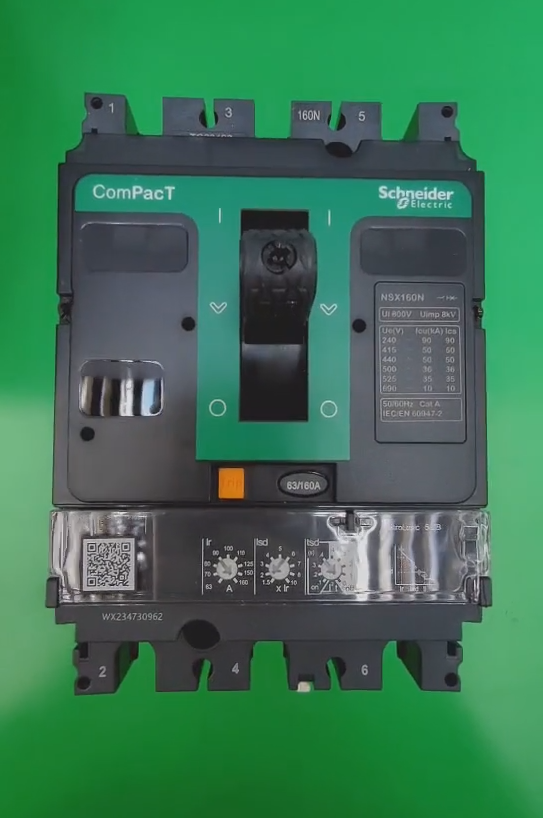

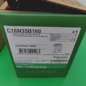

According to the model naming rules of Schneider circuit breakers, the C16N35B160 refers to the Compact NSX series molded case circuit breaker.
기음: May indicate the Compact NSX series.
16: The frame size current is 160A.
N: Breaking capacity grade, usually indicating a breaking capacity of 50kA.
35: May represent specific breaking capacity or technical parameters, such as a short-circuit breaking capacity of 35kA.
비: May indicate the trip type or a specific technical characteristic, but the exact meaning shall be referred to the product manual.
160: The rated current is 160A.
Installation and Operation Guide for Schneider C16N35B160 (Compact NSX Series) 회로 차단기
- 설치 전 준비
- Product Confirmation
Verify model parameters: Confirm that the circuit breaker belongs to the Schneider Compact NSX series, with a frame size current of 160A, a breaking capacity of 50kA (Class N), and a rated current of 160A. The trip type shall be determined based on the actual marking (Type B features a magnetic trip curve, suitable for protecting precision electronic equipment).
Inspect product condition: Check for no external damage, no oxidation on the terminals, flexible operating handle (clear ON/OFF positions), and complete accessories (such as trippers, 보조 접점) that match the model.
- 환경 요구 사항
주변 온도: -5℃~+40℃ (When the temperature exceeds 40℃, the rated current shall be derated in accordance with the product manual. 예를 들어, derate by 1% per 1℃ increase in the range of 40℃~60℃).
Installation location: No dust, 부식성 가스, flammable and explosive environment, and the altitude shall not exceed 2000m (Derating is required when the altitude exceeds the limit; derate by 5% per 1000m increase in the range of 2000m~4000m).
Mounting surface: Vertical installation (tilt angle ≤5°). The mounting surface shall be flat, firm, and capable of withstanding the weight of the circuit breaker and short-circuit impact.
- Preparation of Tools and Materials
도구: Torque wrench (recommended specification: 2.5~10N·m), 드라이버 (Phillips/slotted), 와이어 스트리퍼, 압착 도구, 절연 테이프, 멀티미터.
Materials: Copper busbar/cable (cross-section shall match the 160A rated current; copper cable is recommended to be ≥35mm², copper busbar ≥25mm×3mm), terminal block (matching the cable specification), fixing bolt (M8~M10, selected according to the thickness of the mounting plate).
- Correct Installation Steps
- Circuit Breaker Fixation
Select the installation location: Close to the power supply side, with reserved operating space (no obstacles within ≥10cm around the circuit breaker, and unobstructed handle operation stroke).
Fixing method: Fasten the circuit breaker base to the metal mounting plate with bolts. The torque value shall comply with the requirements of the product manual (usually 8~10N·m for M8 bolts) to ensure firm installation without loosening.
- 주회로 배선
(1) 배선사양
Polarity requirements: Top entry wiring (connect the power supply side to the upper terminals L1/L2/L3 of the circuit breaker, and the load side to the lower terminals T1/T2/T3). Reverse connection is strictly prohibited (그렇지 않으면, the reliability of the tripper action will be affected).
Cable processing: Strip the cable insulation layer to a length of 5~8mm, ensuring no oxidation or loose strands on the conductor. If copper busbars are used, polish the contact surfaces and tin-plate them.
Wiring torque: Tighten the bolts according to the cable specification. The corresponding torque for 35mm² copper cables is 12~15N·m. Avoid insufficient torque causing excessive contact resistance and heating, or excessive torque damaging the terminals.
(2) 지침
Three-phase cables shall have the same specification and be arranged neatly to avoid cross-interference with other circuits (such as control circuits).
배선 후, gently pull the cables to confirm no loosening.
- Auxiliary Circuit Wiring (해당되는 경우)
Tripper wiring: If equipped with electromagnetic tripper, thermal tripper, or intelligent tripper, connect the control power supply in accordance with the product wiring diagram (pay attention to the voltage level, AC220V와 같은, DC24V). Do not reverse the positive/negative poles or phase/neutral lines.
Auxiliary contact wiring: When auxiliary normally open/normally closed contacts are used for signal feedback or interlock control, wiring shall be carried out according to the requirements of the control circuit. Ensure that the contact capacity matches (usually AC220V/5A, DC24V/3A) to avoid contact burnout due to overload.
- Accessory Installation (해당되는 경우)
If equipped with undervoltage release or shunt release, install them before the main circuit wiring. The torque of the fixing bolts shall comply with the requirements of the accessory manual (usually 4~6N·m).
설치 후, check the matching clearance between the accessories and the circuit breaker to ensure smooth operation of the accessories without jamming when the circuit breaker is switched ON/OFF.
III. Commissioning Before Operation
- Manual Operation Test
Opening operation: Toggle the handle to the “끄다” 위치, and check whether the circuit breaker is completely opened and whether the state of the auxiliary contacts is switched (measurable with a multimeter).
Closing operation: Toggle the handle to the “에” 위치, confirm that the closing is in place, the handle is locked reliably, and there is no automatic opening phenomenon.
Energy storage operation (for electric energy storage type): Connect the energy storage power supply, observe the energy storage indicator light. After the energy storage is completed (indicator light is on), close the circuit breaker manually or electrically to confirm that the energy storage mechanism works normally.
- Tripper Parameter Verification
Thermal tripper (과부하 보호): Adjust the trip current according to the rated current of the load (the default trip current of C16N35B160 is 160A. Special tools are required for adjustment if necessary; do not forcefully twist it).
Magnetic tripper (단락 보호): The short-circuit trip current of Type B trip curve is 3~5In (In=160A), 즉., 480A~800A. No manual adjustment is required. If the load type is special (such as motor starting), confirm whether the trip curve matches.
- Power-on Test
No-load power-on: Disconnect the load, connect the power supply, and measure whether the voltage at the input and output ends of the circuit breaker is normal (balanced three-phase voltage without phase loss).
Load test: Gradually apply the load, observe the operation status of the circuit breaker for no heating or abnormal noise. Use a multimeter to measure the balanced three-phase current and confirm no overload.
Short-circuit simulation test (선택 과목, to be operated by professionals): Connect a dedicated short-circuit test device on the load side to simulate a short-circuit fault. Confirm that the circuit breaker can open quickly (opening time ≤0.1s) without arc leakage.
- Correct Operation Specifications
- Operation Requirements
Normal opening and closing: For manual operation, toggle the handle to the corresponding position decisively to avoid contact ablation caused by mid-way pause. For electric operation, ensure stable control signals to avoid frequent start-stop.
After tripping due to fault: If the circuit breaker trips due to overload or short-circuit, the fault cause (such as load short-circuit, 초과 적재) must be identified and eliminated before closing. Forced closing is prohibited.
Prohibition of breaking under load: Do not use the circuit breaker to directly break loads exceeding the rated current. If it is necessary to break large-current loads, it shall be used in conjunction with contactors.
- Load Matching Principles
Applicable loads: Type B trip curve is suitable for protecting loads without inrush current, such as precision electronic equipment and lighting circuits. It is strictly prohibited to use for loads with large starting current, such as motors and transformers (그렇지 않으면, false tripping will occur).
과부하 보호: The long-term operating current of the load shall not exceed the rated current of the circuit breaker (160에이). If the load has periodic overload, select a circuit breaker with a higher trip curve (such as Type C, D형) or increase the rated current of the circuit breaker.
- 안전 예방 조치
Wear insulating gloves and insulating shoes and use insulated tools during operation to avoid electric shock.
Do not touch the terminals and internal components when the circuit breaker is in operation. For maintenance, the power supply must be disconnected first, the absence of voltage must be verified, and a “No Closing” sign shall be posted.
Do not privately modify the internal structure of the circuit breaker (such as replacing the tripper, adjusting trip parameters), 그렇지 않으면, the protection performance will be affected and safety accidents will be caused.
- 유지 관리 및 문제 해결
- 정기점검
일일점검: Conduct inspection once a week. Observe the circuit breaker for no heating or discoloration, normal handle position, and no abnormal noise.
Monthly inspection: Use a multimeter to measure the temperature of the terminals (normal operating temperature ≤70℃). Check for no loosening of cable joints and good contact of auxiliary contacts.
Annual maintenance: Disconnect the power supply, clean the dust on the surface of the circuit breaker (use a dry brush; water or organic solvents are prohibited). Check the flexibility of the tripper action and test the ON/OFF status of the auxiliary contacts.
- 일반적인 오류 문제 해결
| 결함 현상 | 가능한 원인 | 솔루션 |
| 폐쇄 실패 | 1. Load short-circuit not eliminated; 2. Tripper not reset; 3. Mechanical mechanism jamming; 4. Auxiliary circuit power supply fault (electric type) | 1. Identify and repair the load short-circuit point before closing; 2. Manually toggle the handle to the open position and reset; 3. Disassemble the circuit breaker, remove foreign objects from the mechanical mechanism, and apply lubricating oil; 4. Inspect the auxiliary circuit power supply and restore normal voltage |
| Frequent tripping | 1. Load overload; 2. Mismatched trip curve; 3. Loose wiring causing heating; 4. Tripper fault | 1. Reduce the load current to avoid long-term overload; 2. Replace the circuit breaker with a matching trip curve (예를 들어, Type C for motor loads); 3. Re-tighten the terminals and check if the cable cross-section is sufficient; 4. Replace the faulty tripper |
| Heating during operation | 1. Loose wiring leading to excessive contact resistance; 2. Insufficient cable cross-section; 3. Excessively high ambient temperature; 4. Internal fault of the circuit breaker | 1. Tighten the terminals and re-crimp the cables; 2. Replace the cable with the required specification (≥35mm² copper cable); 3. Improve ventilation conditions to reduce the ambient temperature; 4. Disassemble and inspect internal components, replace the circuit breaker if necessary |
| Auxiliary contact failure | 1. Contact burnout due to overload; 2. Contact oxidation or dust accumulation; 3. 느슨한 배선 | 1. Replace the auxiliary contacts and ensure the contact capacity matches; 2. Polish the contacts with fine sandpaper and clean the dust; 3. Tighten the auxiliary circuit wiring |
- Important Notes
- Installation and maintenance must be performed by qualified electrical professionals, and the Code for Construction and Acceptance of Low-voltage Electrical Installations in Electrical Device Installation Engineering (GB 50254) shall be strictly followed.
- The breaking capacity and trip parameters of the circuit breaker shall match the circuit design. Do not use the circuit breaker beyond its specification, 그렇지 않으면, it cannot play a protective role.
- If it is necessary to replace the circuit breaker or accessories, it is recommended to use Schneider original accessories or compatible alternative products such as Chint NM1 series (parameters must be confirmed to be consistent). Non-standard accessories are prohibited.
- If any abnormality occurs during product operation, disconnect the power supply immediately, contact Schneider technical support or professional maintenance personnel, and do not disassemble it without authorization.
 from Schneider Electric’s EasyPact EZS+ Series (Dunhuang Series). Its official order code is EZSS630F3630, with the full model description EZS-S630 36kA TM630D 3P3D, designed for power distribution protection.")
, 배전 보호를 위한 핵심 부품. 과부하를 제공합니다, 3상 회로에 대한 단락 및 지락 보호, 산업 및 상업용 배전 시스템의 핵심 보호 장치입니다..")
 LS일렉트릭에서 제작한 (㈜LS산전 / LG산전).")


")


NH42-63-318x560.png "CHINT PC형 자동절환스위치 (ATS)NH42-63/4SZ")


