 접촉기,회로 차단기,태양광 인버터,전기 계량기,태양 전지

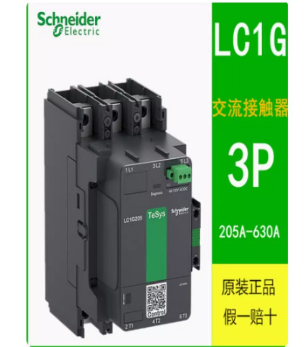

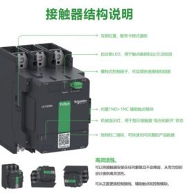
3‑pole contactor from domestic TeSys Giga series, AC‑3 475A/440V, coil 100–250V AC/DC wide voltage, standard 1NO+1NC auxiliary contacts. Suitable for high‑power motor control and power switching. Supports contact wear diagnosis and can be used with LR9G series thermal relays.
1 기본 매개변수 & Naming Explanation
| 목 | 사양 | 설명 |
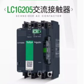
| 모델 | LC1G475KUEC | Domestic TeSys Giga series, 3피(3아니요), AC‑3 ≤440V 475A, 100–250V AC/DC coil |
| 시리즈 | TeSys Giga (LC1G) | New generation high‑power contactor from Schneider, replaces old LC1D475 |
| 폴란드 | 3피(3아니요) | 3‑pole normally open, for three‑phase circuit control |
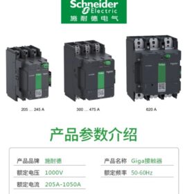
| 정격전류 | 475에이 (AC‑3, ≤440V) | Rated operational current of main circuit |
| Coil voltage | 100–250V AC/DC | Wide‑voltage design, compatible with various control supplies |
| Coil frequency | 50/60헤르츠 | Compatible with global mains frequencies |
| 보조 접점 | 1NO+1NC | 표준 구성, expandable with more aux contacts |
| Applicable standards | IEC 60947-4-1, GB/T 14048.4 | Complies with international and national standards |
| Version | China version (suffix C) | Designed for domestic market; no UL certification; global version without C |
2 Key Performance Data
| Utilization category | 정격 출력 (400다섯) | 정격 출력 (440다섯) | Short‑time withstand current |
| AC‑3 (normal motor starting/running) | 대략. 250kW | 대략. 265kW | 10500에이 (1에스) |
| AC‑4 (frequent starting/reversing) | 대략. 180kW | 대략. 190kW | – |
| AC‑1 (resistive load) | 대략. 475kW | 대략. 475kW | – |
3 응용 & 특징
응용
Direct starting, forward/reverse control, star‑delta starting of high‑power three‑phase asynchronous motors
Industrial power switching and distribution system control
Inductive load control with power factor ≥ 0.95
Heavy‑duty industries: building electrical, 야금, 화학적인, 채광, 등.
주요 특징
- High performance: Up to 620A at AC‑3, 1050A at AC‑1 for heavy‑duty applications
- Smart diagnosis: Built‑in contact wear detection for predictive maintenance
- Wide‑voltage coil: 100–250V AC/DC reduces spare parts inventory
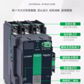
- 모듈형 디자인: Supports various accessories (aux contacts, mechanical interlock, surge suppressor, 등.)
- Safe & reliable: Excellent arc extinguishing, 혹독한 산업 환경에 적합
4 설치 & Wiring Information
Mounting dimensions (China version LC1G475C)
너비: 대략. 140mm
키: 대략. 270mm
깊이: 대략. 150mm
설치: Standard 35mm DIN rail or screw mounting
무게: 대략. 10.6kg
Wiring requirements
- Main circuit terminals: Suitable for copper/aluminum cables; crimping lugs recommended
- Control circuit terminals: Suitable for 1.5–2.5mm² control cables
- Clearance: ≥50mm left & right, ≥100mm top & bottom for proper heat dissipation
5 액세서리 호환성 & Matching Products
| Accessory type | Recommended model | 기능 |
| Thermal overload relay | LR9G475 | Matches LC1G475KUEC, provides motor overload protection |
| Mechanical interlock | For LC1G series | For forward/reverse control; prevents simultaneous closing |
| Surge suppressor | For LC1G series | Protects coil against voltage spikes |
| Auxiliary contact module | For LC1G series | Expands NO/NC contacts for complex control |
6 브랜드 간 대안
| 상표 | Replacement model | Match level | 메모 |
| 씨줄 | AF460‑30‑11 (100–250V AC/DC) | 높은 | Rated 460A, close to 475A; verify load margin |
| 지멘스 | 3RT2076‑6AP36 (100–250V AC/DC) | 높은 | Sirius series, 475에이, fully compatible |
| 친트 | CJX1‑475/22 (100–250V AC/DC) | 중간 | 국내 대안; slight performance differences, cost‑effective |
| 창수 스위치 | CK3‑475 (100–250V AC/DC) | 중간 | Premium domestic brand, high cost‑performance |
7 설치 & Commissioning Tips
- Pre‑installation inspection
Verify model, rated parameters and control supply match
Check for physical damage, 접촉 산화
Ensure flat mounting surface and secure rail
- Installation steps
DIN 레일: Align to 35mm rail, press firmly until locked
Screw mounting: Use M6 screws, torque 8–10N·m
배선: Main circuit first, then control circuit; observe terminal torque
- 시운전 & testing
No‑load test: Apply control power; check smooth operation, 비정상적인 소음
Load test: Run under load; monitor current, coil temperature
Aux contact test: Verify NO/NC switching and contact resistance
- Maintenance recommendations
Regularly inspect contact wear; 마모되면 교체 >1mm
Clean arc chamber; remove dust and metal particles
Check coil insulation resistance ≥1MΩ
Retighten all terminals to avoid overheating
8 Selection Notes
- Select contactor according to load type (AC‑3/AC‑4/AC‑1)
- For motor control: Contactor rated current ≥ 1.1 × motor rated current
- For frequent starting/reversing (AC‑4): Derate by 20–30%
- For unstable control supply: Prefer wide‑voltage coil models
- When used with thermal relay: Ensure matching ratings
Installation Manual – Schneider Domestic TeSys LC1G475KUEC 3‑Pole Contactor
Doc No.: DOCA0189ZH‑04 (based on official Schneider TeSys Giga installation guide)
Applicable model: LC1G475KUEC (domestic TeSys Giga 3‑pole contactor)
Version: January 2023
⚠️ Safety Warnings (Must Read)
| Hazard type | Preventive measures |
| Electric shock / explosion / arc flash hazard | 1. Disconnect all power (main and control) before installation |
| 2. Only qualified electricians may operate | |
| 3. Use appropriate PPE | |
| 4. Comply with electrical safety codes (예를 들어, NFPA 70E) | |
| 5. Install in non‑hazardous areas (IEC 60079) | |
| Mechanical injury hazard | 1. Contactor approx. 10.6kg; support during installation |
| 2. Avoid finger pinching between contactor and mounting plate/rail | |
| 3. Use proper tools to prevent slipping injury | |
| Overheating hazard | 1. Maintain required clearances: ≥50mm sides, ≥100mm top/bottom |
| 2. Do not store flammables near contactor | |
| 3. Inspect cooling regularly |
1 Product Overview
1.1 Product Identification
모델: LC1G475KUEC
시리즈: Domestic TeSys Giga (LC1G)
폴란드: 3피 (3아니요, 3‑pole normally open)
정격전류: AC‑3 475A (440다섯)
Coil voltage: 100–250V AC/DC (wide voltage)
보조 접점: 1NO+1NC standard
Standards: IEC 60947-4-1, GB/T 14048.4
Version: China version (suffix C; no UL certification)
1.2 치수 (Unit: mm)
| 차원 | 값 |
| 너비 | 140 |
| 키 | 270 |
| 깊이 | 150 |
| 장착 구멍 간격 | 100×120 (bottom hanging + fixing holes) |
2 Pre‑Installation Preparation
2.1 도구
십자 드라이버 (PH3)
Hex key (per fixing screw size)
Torque wrench (5–20N·m range)
Wire stripper (1.5–2.5mm² control & large main cables)
Crimping tool (for cable lugs)
Multimeter (coil resistance & insulation check)
Spirit level
2.2 Materials
Mounting plate (metal, thickness ≥3mm, flat, burr‑free)
M6 mounting screws (min. 4 pcs)
Cable lugs (for main circuit cables)
Control cable (1.5–2.5mm² copper)
Main cable (≥150mm² copper recommended)
Insulation tape / heat‑shrink tubing
Marker pen
2.3 환경 요구 사항
| 매개변수 | Requirement |
| Temperature | -5°C ~ +40°C (operating); -25°C ~ +55°C (storage) |
| 습기 | ≤95% (비응축) |
| 고도 | 2000m 이하 (derate above) |
| Pollution degree | 2 (industrial environment) |
| 진동 | ≤5.9m/s² (5–150Hz) |
| Inclination | ≤30° from vertical |
2.4 Product Inspection
- Check packaging and transport damage
- Verify model label (LC1G475KUEC)
- Inspect contacts for oxidation, pitting, foreign matter
- Manually actuate armature; check smooth operation
- 멀티미터로 코일 저항 측정
- Test auxiliary contact switching
3 Installation Procedure (Surface Mounting)
메모: Domestic LC1G475KUEC supports surface mounting only; not for DIN rail.
3.1 Mounting Plate Drilling (선택 과목)
- Mark holes at 100×120mm
- Drill diameter: φ6.5mm (for M6)
- Deburr after drilling
3.2 Hanging & Fixing
- Hang: Locate bottom hanging holes onto mounting plate pins/screws
- Preliminary fix: Hand‑tighten top M6 screws
- Final fix: Torque all 4 screws to 3±0.3N·m (top‑down, diagonal)
- Level check: Ensure inclination ≤30°
3.3 Accessory Installation (Aux Contacts / Mechanical Interlock)
- 보조 접점
Disconnect control power
Align and push into top slot until click
Verify secure locking
- Mechanical interlock
Keep ≥50mm between two contactors
Mount interlock on sides
Adjust to prevent simultaneous closing
Test manually
4 Wiring Procedure
4.1 Pre‑Wiring Notes
- Confirm all power disconnected
- Main cables must use proper crimp lugs
- Control cable strip length: ~8–10mm
- Sequence: Main circuit first, then control
4.2 주회로 배선 (3피, L1/L2/L3 → T1/T2/T3)
- Open main terminal cover
- Insert lugged cables
- 토크:
Copper: 12±1N·m
Aluminum: 14±1N·m (with anti‑oxidant)
- Securely tighten; check by gentle pull
- Close terminal cover
4.3 제어 회로 배선 (Coil A1/A2, Aux NO/NC)
- Open control terminal cover
- 코일:
A1: Control supply +/Line
A2: Control supply –/Neutral
- Aux contacts:
아니요: 13–14 (holding, indication)
NC: 21–22 (interlock, fault)
- Control terminal torque: 2±0.2N·m
- Close cover
4.4 Wiring Diagram
5 Mounting with Thermal Relay (LR9G475)
5.1 Direct Installation
- Confirm matching: LC1G475KUEC + LR9G475
- Align thermal relay to top slot
- Push down until click
- Check secure mounting
- Connect pre‑installed busbars
- Torque busbar screws: 8±0.8N·m
5.2 Wiring Notes
- Main: Power → Contactor → Thermal relay → Motor
- 제어: Thermal relay NC (95–96) in series with contactor coil
- Set thermal relay current to motor rated current
6 시운전 & 테스트
6.1 No‑Load Test
- Apply control power (main open)
- Check smooth closing, no abnormal noise
- Verify aux contact switching
- Check rapid opening
- Repeat 3–5 times
6.2 부하 테스트
- Apply main power
- Start motor; check current within rating
- Monitor coil temperature ≤60°C after 1h
- Check terminal temperature ≤70°C (infrared)
- Simulate overload; verify relay trip
6.3 Contact Wear Diagnosis (LC1G Feature)
- Monitor via auxiliary contacts
- Warning when wear >1mm
- Replace contactor promptly
7 유지 & Service
7.1 Routine Inspection (모든 6 개월)
- De‑energize; inspect for dirt, damage
- Clean arc chamber (compressed air ≤0.3MPa)
- Check contact resistance ≤500μΩ
- Check coil insulation ≥1MΩ (500V megger)
- Retighten terminals
- Test operation
7.2 Replacement Schedule
| Part | Interval | Replacement standard |
| 주요 연락처 | 1–2 years | Wear >1mm or resistance >500μΩ |
| Aux contacts | 2–3 years | Poor switching |
| 코일 | 3–5 years | Insulation aging, weak closing |
| Arc chamber | 5 연령 | Degraded performance |
7.3 문제 해결
| Symptom | Possible causes | 해결책 |
| Contactor fails to close | 1. No control power | 1. Check wiring |
| 2. Coil fault | 2. Replace coil | |
| 3. Mechanical jam | 3. Clean & lubricate | |
| Loud noise on closing | 1. Dirty iron core | 1. Clean surfaces |
| 2. Broken ring | 2. Replace ring | |
| 3. 낮은 코일 전압 | 3. Check supply | |
| Contacts overheating | 1. Loose terminals | 1. Retighten |
| 2. Oxidized contacts | 2. Clean/replace contacts | |
| 3. 초과 적재 | 3. Check load | |
| Slow opening | 1. Fatigued spring | 1. Replace spring |
| 2. Mechanical jam | 2. Clean mechanism | |
| 3. Residual magnetism | 3. Check coil |
8 안전 & 환경
8.1 Safe Disposal
- Disconnect all power before scrapping
- Remove all wiring
- Separate metal & plastic for recycling
- Contacts contain silver alloy; recycle as precious metal
8.2 Environmental Compliance
RoHS 준수; free of Pb, Hg, 등.
Plastic housing recyclable
Dispose per local regulations
9 Appendix – Technical Data
| 매개변수 | 값 |
| Rated operational current (AC‑3, 400다섯) | 475에이 |
| 정격 출력 (400다섯, AC‑3) | 250kW |
| Short‑time withstand current (1에스) | 10500에이 |
| Coil voltage | 100–250V AC/DC |
| Coil power | Inrush: ~200VA, Sealed: ~20W |
| Aux contact rated current | 5에이 (AC‑15, 220다섯) |
| 기계적 수명 | 10,000,000 운영 |
| 전기적 수명 (AC‑3) | 1,000,000 운영 |


")

NH42-63-318x560.png "CHINT PC형 자동절환스위치 (ATS)NH42-63/4SZ")


