 Контактор,автоматический выключатель,солнечный инвертор,электрический счетчик,солнечные батареи

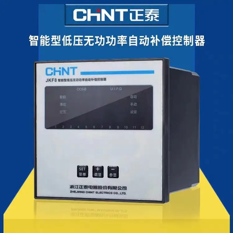


It is a supporting device launched by Chint Электрический for low-voltage shunt capacitor panel devices. Suitable for AC power distribution systems with a rated voltage of 380V and a frequency of 50Hz, it is used to control the automatic switching of shunt capacitors, so as to improve voltage quality and reduce power loss.
Функциональные особенности
Hybrid Control: Adopts reactive power and power factor hybrid control to ensure reliable switching under low-load conditions and avoid switching oscillation.
Parameter Display: Real-time display of grid condition parameters such as power factor, Напряжение, текущий, active power and reactive power.
Polarity Identification: Automatically identifies the polarity of sampling signals to prevent reverse polarity connection.
Overvoltage and Undervoltage Protection: When the grid voltage is lower than 300V or exceeds the set value, the connected capacitor banks will be cut off step by step within 5 seconds automatically, and the voltage value will be displayed.
Under-current Protection: When the secondary signal of the current transformer is less than 150mA, the capacitor switching will be blocked, and the connected capacitor banks will be cut off step by step within 5 seconds at the same time.
Switching Lockout: The switching lockout time of the same capacitor bank is 3 minutes to ensure capacitor discharge.
Self-test Function: Equipped with cyclic self-test function, facilitating the factory test of capacitor panels.
Operation Mode Switching: Supports manual and automatic operation mode switching.
Технические параметры
Sampling Voltage: 380 В переменного тока (±20%)
Sampling Current: ≤5A
Номинальная частота: 50Hz±5%
Sensitivity: ≤150mA (minimum sampling current)
COSφ Preset: Continuously adjustable from 0.85 к 0.95, factory preset at 1.00
Overvoltage Preset: Adjustable from 400V to 456V, factory preset at 430V
Delay Time Preset: Adjustable from 5s to 120s, factory preset at 30s
Output Contact Capacity: 380 В переменного тока, 3А (резистивная нагрузка) or AC 220V, 5А (резистивная нагрузка)
Selection Information: The JKF8 series controllers are available in two types with 6 switching loops and 12 switching loops for capacitors, and the number of loops can be set.
Installation Method of Chint NKF8 Intelligent Low-Voltage Reactive Power Automatic Compensation Controller
- Pre-installation Preparation
- Confirmation of Environmental Requirements
- The installation environment shall meet the following requirements: temperature ranging from -10℃ to +55℃, relative humidity ≤85% (нет конденсата), and avoid places with dust, corrosive gas, strong electromagnetic interference (например, keep away from frequency converters, large contactors, и т. д.) and severe vibration.
- The installation location shall be well-ventilated, with a heat dissipation space of ≥10cm reserved (at the top, bottom and both sides of the controller). Avoid direct sunlight or proximity to heat sources (например, reactors and high-power resistors in capacitor cabinets).
- Preparation of Tools and Accessories
- Инструменты: крестовая отвертка (PH2), flathead screwdriver, crimping tool, wire stripper, multimeter (AC voltage range, continuity range), динамометрический ключ (рекомендуется).
- Аксессуары: Installation accessories included with the controller (guide rail buckles/fixing screws), copper bars/wires (selected according to wiring specifications), wiring terminals (cold-pressed terminals are recommended), grounding wires (yellow-green double color, cross-sectional area ≥1.5mm²).
- Equipment Inspection
- After unpacking, check the appearance of the controller: no damage or cracks on the shell, clear panel display window, no oxidation or looseness of wiring terminals.
- Verify that the product model and specifications (например, number of loops, номинальное напряжение) are consistent with the design requirements, and the accessories (instruction manual, mounting bracket) полны.
- Этапы установки
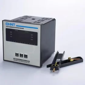
- Selection of Installation Methods
The Chint NKF8 controller supports two installation methods, and guide rail installation (compatible with standard 35mm DIN rails) предпочтительнее:
- Guide Rail Installation (commonly used in capacitor cabinets)
Confirm that the mounting beam in the capacitor cabinet is a 35mm standard guide rail (thickness 1.5~2.0mm), and clean up debris on the surface of the guide rail.
Clip the hook at the top of the controller into the upper edge of the guide rail, press the bottom of the controller downward until a “щелкнуть” sound is heard to lock it in place. Ensure that the controller is free from looseness and can slide slightly along the guide rail (facilitating wiring adjustment).
- Screw Fixing Installation (for scenarios without guide rails)
Drill holes (aperture φ4.5mm) on the mounting panel according to the spacing of the mounting holes at the bottom of the controller (refer to the product manual, usually 60~80mm).
Pass M4 screws through the mounting holes, fasten them with flat washers and spring washers, and control the torque within 1.2~1.5N·m. Ensure that the controller is installed horizontally (the panel is perpendicular to the ground) without inclination.
- Характеристики проводки (core step, power-off operation is mandatory!)
Before wiring, disconnect the main power supply of the capacitor cabinet, verify that there is no voltage, and then proceed with construction. The wiring sequence is: power supply wiring → sampling signal wiring → control output wiring → grounding wiring.
- Power Supply Wiring (controller working power supply)
– Rated working voltage of the controller: AC 220V or AC 380V (check the product nameplate, the default is mostly AC 220V).
– Lead the power cord of the corresponding voltage from the secondary circuit power switch of the capacitor cabinet, strip off the insulation layer of the wire (about 6~8mm), and connect it to the “л” (live wire), “Н” (neutral wire, for 220V) или “L1, Л2” (for 380V) terminals of the controller.
– Selection of power cord cross-sectional area: copper core wire ≥1.0mm². Press the terminals tightly during wiring to avoid heating caused by poor contact. If it is a 380V power supply, pay attention to the correct phase sequence, and there is no need to distinguish phase sequence polarity.
- Sampling Signal Wiring (voltage and current sampling, determining compensation accuracy)
Voltage Sampling
Lead the AC 380V sampling voltage from the busbar of the power distribution system (usually the ABC three-phase at the incoming line side of the capacitor cabinet) and connect it to the “Ua, Ub, УК” terminals of the controller (three-phase sampling, no phase loss is allowed).
Cross-sectional area of voltage sampling wire: copper core wire ≥1.0mm², the length should not exceed 10m. If extension is required, shielded wires should be used and the shielding layer should be grounded.
Current Sampling
Current sampling is taken from the secondary side of the current transformer (Коннектикут) at the incoming line side of the power distribution system. The CT transformation ratio must be consistent with the controller parameter settings (to be matched during subsequent commissioning).
Connect the “K1” terminal of the CT secondary side to the “Ia” terminal of the controller, and the “K2” terminal to the “Ib” terminal of the controller (single-phase sampling, usually phase A or phase C. If three-phase sampling is required, check whether the product supports it). Opening of the CT secondary side is strictly prohibited (short-circuit the CT secondary side before wiring, and remove the short-circuit after wiring is completed).
Cross-sectional area of current sampling wire: copper core wire ≥1.5mm², shielded wires are preferred. The shielding layer should be grounded at one end (near the CT side). The length should be controlled within 15m, and parallel laying with power lines should be avoided.
- Control Output Wiring (connecting capacitor switching switches)
– The output terminals of the controller are relay contacts, used to control the switching of capacitor banks (например, AC contactors, composite switches, thyristor switches). The terminal marks are usually “1~n” (corresponding to 1~n loops, такой как 6 loops and 12 loops) и “КОМ” (общий терминал).
– Control wiring of each capacitor loop: lead the common wire from the “КОМ” terminal of the controller and connect it to one end of the coil of the switching switch; lead the control wire from the corresponding loop terminal of the controller (например, “1”) and connect it to the other end of the coil of the switching switch.
– Selection of control wire cross-sectional area: determined according to the coil current of the switching switch, usually copper core wire ≥1.0mm². If the switch coil voltage is AC 220V/380V, pay attention to the matching between the coil power supply and the controller output contact capacity (NKF8 output contact capacity: AC 380V/3A or AC 220V/5A for resistive loads. For inductive loads, требуется снижение мощности, or an intermediate relay should be installed to expand the capacity).
- Grounding Wiring (safety requirement)
– The controller shell is equipped with a grounding terminal (marked with “ЧП” or grounding symbol), which must be connected to the protective grounding bar of the capacitor cabinet with a yellow-green double-color copper core wire (cross-sectional area ≥1.5mm²), and the grounding resistance should be ≤4Ω.
– Ensure that the grounding wire is free from breakage and poor contact, and the grounding bar is reliably connected to the cabinet body and the cabinet body to the ground grounding system.
- Wiring Review
- Use the continuity range of the multimeter to check whether each wiring terminal is pressed tightly, without looseness or short circuit (например, no conduction between the power supply terminal and the sampling terminal).
- Verify that the voltage sampling phase sequence and current sampling polarity are correct (текущий “K1→Ia”, “K2→Ib”. Reverse connection will lead to compensation logic errors).
- The control output loops are in one-to-one correspondence with the capacitor bank loop numbers to avoid switching confusion.
III. Power-on Commissioning and Inspection
- Final Inspection Before Power-on
- Confirm that all wiring is completed without omission or wrong connection, tools have been removed from the capacitor cabinet, and the cabinet door is closed properly.
- Close the main power supply and secondary circuit power switch of the capacitor cabinet, and use a multimeter to measure the voltage of the controller power supply terminal, which should meet the rated voltage requirement (error ±10%).
- Power-on Commissioning Steps
- After the controller is powered on, the panel display screen lights up and enters the default display interface (usually displaying parameters such as power factor, voltage and current) without fault alarms (например, “Err” code).
- Press the panel buttons to enter the parameter setting interface and verify the key parameters:
Current Transformer Ratio (CT Ratio): consistent with the actual CT specifications (например, if CT is 400/5, set it to 80).
Switching Delay: default 30s (can be adjusted according to the capacitor discharge time, it is recommended to be ≥15s).
Target Power Factor Value: default 0.95 (adjustable between 0.85 и 0.99).
Overvoltage Protection Value: default 430V (can be adjusted according to the grid voltage, it is recommended to be 410~450V).
- Simulated Load Test
Manual Mode: switch the controller to the “Руководство” gear, press the switching buttons one by one, and observe whether the switching switches of the corresponding capacitor loops are closed/disconnected. The panel displays the status of the corresponding loops (например, “1 ON”, “2 OFF”).
Automatic Mode: switch to the “Автоматический” gear, observe that the controller automatically switches the capacitor banks according to the power factor without frequent switching (oscillation) or refusal to operate, and the voltage and current parameters are displayed stably.
- Поиск неисправностей
- If there is no display after power-on: check whether the power supply wiring and power supply voltage are normal, and whether the controller power supply fuse is blown (if any).
- If the displayed power factor is abnormal (например, fixed at 0 или 1): check whether the voltage sampling is phase-loss or the current sampling polarity is reversed.
- If automatic switching is not possible: check whether the control output wiring and the switching switch coil power supply are normal, and whether the controller parameter settings are correct.
- Меры предосторожности
- The entire construction process shall be carried out by professional personnel with low-voltage electrician operation certificates. Strictly follow the process of “power-off → voltage verification → tagging → wiring” to avoid electric shock accidents.
- Opening of the current transformer secondary side is strictly prohibited. Short-circuit the CT secondary side during wiring, and remove the short-circuit after wiring is completed.
- Avoid damage to the wire insulation layer during wiring to prevent short circuit. If inductive loads (например, contactor coils) are connected to the control output loop, a surge absorber (например, RC absorber) should be connected in parallel to protect the controller contacts.
- После установки, post the wiring diagram and parameter setting table in the capacitor cabinet for subsequent maintenance.
- Reference Materials
For more detailed wiring diagrams and parameter setting instructions, refer to the Chint NKF8 Intelligent Low-Voltage Reactive Power Automatic Compensation Controller User Manual attached to the product, or contact Chint technical support to obtain electronic materials. If complex scenarios are encountered during installation (например, multi-capacitor cabinet linkage, special power grid environment), it is recommended to communicate with technical personnel in advance to confirm the scheme.


")


")

NH42-63-318x560.png "Автоматические переключатели резерва типа PC CHINT (АТС)НХ42-63/4СЗ")


