
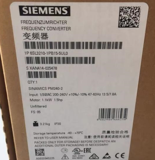

The 6SL3210-1PB15-5UL0 is a power module of the Siemens SINAMICS G120 series. Below is its key information:
Основные параметрыSiemens 6SL3210-1KE18-8UF1
Suitable Motor Power:
– Heavy overload: 0.75 кВт (200% overload for 3 с, 150% overload for 57 с, 100% overload for 240 с; ambient temperature: -10°C to +50°C).
– Light overload: 1.1 кВт (150% overload for 3 с, 110% overload for 57 с, 100% overload for 240 с; ambient temperature: -10°С до +40°С). Siemens model number 6SL3210-1KE23-2UF1
Power Supply Voltage: 200–240 V ±10%, frequency 47–63 Hz, 1AC/3AC (single-phase input/three-phase output or three-phase input/three-phase output; specific descriptions may vary slightly due to data differences. Generally, three-phase input/output is the mainstream understanding. Here, the module supports three-phase input/output as a common scenario, and the broad description of 1AC/3AC in some materials covers input/output possibilities in different application scenarios, with three-phase being the primary application). Siemens S7-1200 series PLC
Номинальный ток: 6 А.
Класс защиты: IP20.
РазмерыSiemens 6ES7253-1AA22-0XA0 (EM253)
– Some data show 291x100x165 (height x width x depth) мм (FSB size).
– Other descriptions include 114.00×185.00×365.00 мм (differences may exist due to measurement methods or different versions; the former is used as the common description for the module’s own dimensions, while the latter may include packaging or size definitions under different specifications).
Weight: 2.9 KG.
Особенности продуктаSiemens 6ES7235-0KD22-0XA0
– Belongs to the PM240-2 series, with no built-in filter and an integrated brake chopper.
– Control mode: integrated fieldbus; communication supports PROFINET-PN.
Область применения
Suitable for industrial automation control, it can drive various types of motors and is commonly used in scenarios such as drive control for fans, насосы, компрессоры, и т. д.. (specific applications need to be combined with actual system configurations and equipment requirements).
Installation and Wiring Guide for Siemens 6SL3210-1PB15-5UL0 Power Module
- Installation GuideSiemens 6ES7231-5QA30-0XB0 module
- Installation Environment Requirements
Температура окружающей среды: -10°C to +50°C (light overload) or +40°C (heavy overload); derating is required above 40°C.
Влажность: ≤95% relative humidity, нет конденсата.
Высота: ≤1000 m (derating is required for higher altitudes). 6ES7142-5AF00-0BA0 Siemens
Класс защиты: Only suitable for control cabinets with IP20 protection.
Installation Position: Install vertically, leaving at least 100 mm of heat dissipation space on all sides.
- Mechanical Installation Steps
- Монтаж на рельсе: Fix the bottom slot of the module using a DIN rail (TS35/7.5 or TS35/15).
- Screw Fixing: Tighten with M4 screws through the mounting holes on the top of the module (крутящий момент: 0.8–1.0 Nm).
- Module Arrangement: When paralleling multiple units, the spacing between adjacent modules should be ≥25 mm (vertical direction) or ≥100 mm (horizontal direction).
- Wiring Methods
- Power Supply Wiring (Л1/Л2/Л3)
Input Voltage: 200–240 V AC, трехфазный (or single-phase input; refer to the manual for details).
Cable Specification: It is recommended to use 2.5–6 mm² stranded copper wires (selected according to the load current).
Wiring Steps:
- Remove the terminal cover (located on the front of the module).
- Connect the power supply cables to the L1, L2, L3 terminals (no polarity requirement).
- Tighten the terminal screws (крутящий момент: 1.2–1.5 Nm).
- Motor Wiring (U/V/W)
Cable Specification: It is recommended to use 2.5–6 mm² stranded copper wires (needs to match the power supply cables).
Wiring Steps:
- Connect to the U, В, W terminals (corresponding to the three-phase windings of the motor).
- Ensure the motor matches the module’s power (0.75–1.1 kW).
- Brake Resistor Wiring (+/-)
Brake Resistor Requirements: An external brake resistor is required (recommended value: 200Ω/500W).
Wiring Steps:
- Connect the brake resistor to the + and DB terminals (the module has a built-in brake chopper).
- If no braking function is needed, short-circuit the + and DB terminals.
- Проводка цепи управления
Digital Inputs (DI): 6 цифровые входы (support PNP/NPN), default voltage 24V DC.
Analog Input (AI): 1 analog input (0–10V or 0–20mA, requires jumper settings).
Digital Outputs (DO): 2 релейные выходы (rating: 2A/250V AC).
Analog Output (AO): 1 analog output (0–20mA).
Wiring Key Points:
– Lay control cables separately from power cables to avoid interference.
– Use shielded cables with the shield grounded at one end.
- PROFINET Communication Wiring
Interface: Integrated RJ45 interface (X1).
Topology: Supports linear, звезда, or ring topologies.
Wiring Steps:
- Use CAT5e or higher Ethernet cables to connect to a PLC or switch.
- Termination resistor setting: Only activate the termination resistor for the last device in the network (set via a switch on the module).
III. Safety Precautions
- Power-Off Operation: Disconnect the main power supply and wait for at least 5 минуты (for capacitor discharge) before wiring.
- Grounding Requirements: The module’s casing must be reliably grounded (ground resistance ≤10Ω).
- Polarity Check: Ensure correct polarity for power supply and brake resistor wiring.
- EMC Compliance: Use shielded power cables and follow Siemens’ EMC installation guidelines.
- Commissioning Recommendations
- Parameter Setting: Set basic parameters via STARTER or the SINAMICS G120C operation panel (например, P0003=3 to activate expert-level parameters).
- Motor Identification: Perform quick commissioning (P0010=1) and automatic motor identification (P1910=1).
- Operation Test: Run (no-load) first, and only apply load after confirming correct direction and parameters.
For more detailed steps, refer to the Siemens official document 6SL3210-1PB15-5UL0 Operation Manual (document number: A5E30077851).


")


NH42-63-318x560.png "Автоматические переключатели резерва типа PC CHINT (АТС)НХ42-63/4СЗ")

")

