 المقاولين,قاطع الدائرة,الاستشعار,التشفير,بلك,محول

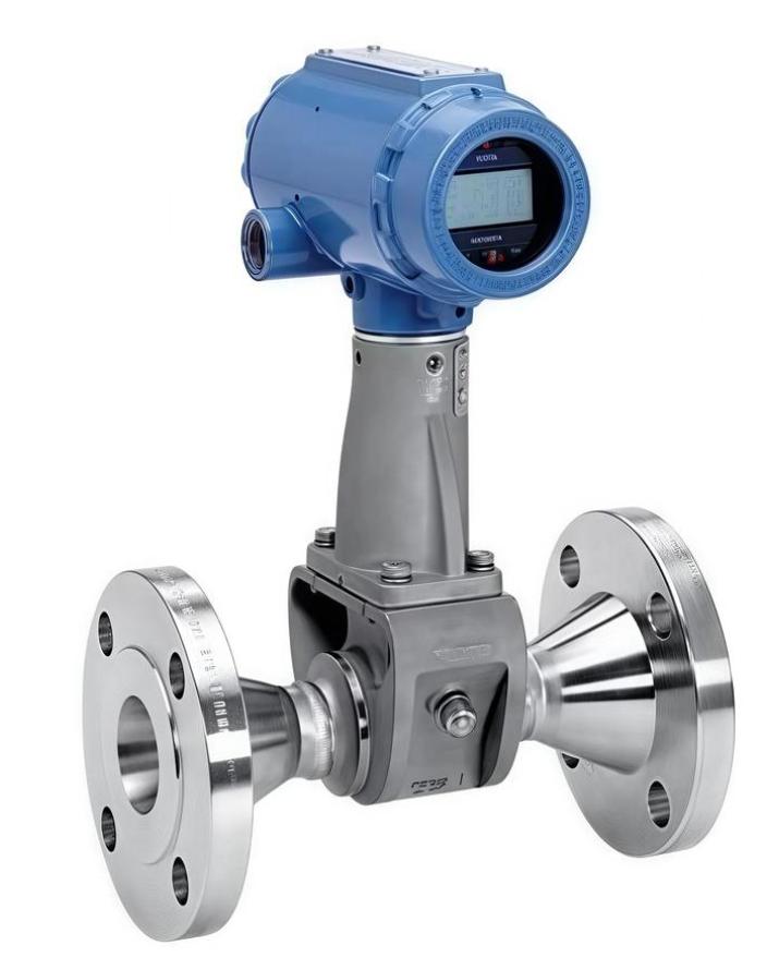
رقم النموذج الكامل: 8800DF010SA1N1D1K8M5Q4
منتج: إيمرسون روزماونت موديل 8800D مقياس الجريان الدوامي ذو الحواف
السوائل المطبقة: السوائل, الغازات, البخار المشبع والمسخن.
فك تشفير رمز النموذج خطوة بخطوة
`8800 د ف 010 س أ1 ن 1 د 1 K8 M5 Q4`
- 8800د: سلسلة المنتجات, جسم مقياس التدفق الدوامي
- ف: نمط اتصال ذو حواف (W = نمط الرقاقة)
- 010: الحجم الاسمي 1 بوصة / DN25
- س: مادة مبللة: 316/316L الفولاذ المقاوم للصدأ (الفولاذ المقاوم للصدأ المصبوب CF3M)
- أ1: شفة القياسية: ASME B16.5 فئة الترددات اللاسلكية150 (فئة أنسي 150 شفة الوجه المرتفعة)
- ن: نسخة درجة الحرارة القياسية: -40درجه مئوية ~ +232 درجه مئوية
- 1: مواد الإسكان: السكن الألومنيوم مع 2 × 1/2-14 إدخالات كابل NPT
- د1: وحدة الالكترونيات: 4-20 مللي أمبير + هارت الإخراج التناظرية, لا يوجد نبض الإخراج
- ك8: شهادة مقاومة للانفجار: شهادة الصينية (إكسد مقاوم للاشتعال + Exia آمن بشكل جوهري, شهادة CNEX)
- م5: رأس الارسال: شاشة LCD رقمية محلية
- س 4: رمز لاحقة اختياري: شهادة السلامة SIL2 + تشخيص العمليات المتقدمة (عملية حرجة)
ملخص المواصفات الرئيسية
القطر الاسمي: DN25 (1″), شفة ANSI Class150
تواصل: 4~20 مللي أمبير + هارت7
مجهزة بشاشة LCD محلية
الحماية من الانفجار: شهادة مزدوجة للسلامة الداخلية والسلامة الداخلية
مستوى سلامة السلامة SIL2, مناسبة لحلقات الأمان SIS
الوسائط القابلة للقياس: بخار, الهواء المضغوط, الماء والسوائل العملية المختلفة
المزايا الهيكلية: تصميم ملحوم بالكامل وغير حشية ومضاد للانسداد; يمكن استبدال المستشعر عبر الإنترنت دون خفض ضغط خط الأنابيب أو إيقاف تشغيله
معلومات تكميلية
- النموذج الأساسي المشترك: 8800DF010SA1N1D1K8M5. تعتبر اللاحقة Q4 بمثابة إضافة اختيارية لشهادة SIL والتشخيصات المتقدمة.
- الصناعات النموذجية: محطات الطاقة الحرارية, الصناعة الكيميائية, تصنيع الأدوية, قياس البخار HVAC.
- تذكير بالاستبدال: عند اختيار الوحدات البديلة, القطر الاسمي, فئة ضغط شفة, يجب أن تكون درجة مقاومة الانفجار وشهادة SIL متطابقة تمامًا.
أبعاد التثبيت - Rosemount 8800DF نوع ذو حواف DN25 (1″, الموديل 8800DF010) أنسي150 الترددات اللاسلكية
تنطبق على النموذج الخاص بك: 8800DF010SA1N1D1K8M5Q4 (DN25 Class150 متر دوامة ذات حواف)
> جميع البيانات مصدرها وثيقة ايمرسون الرسمية 00813-0106-4004
- الأبعاد الشاملة الحرجة (وحدة: مم)
| المعلمة | DN25 1″ Class150 RF (8800DF010 A1) | ملاحظات |
| Face-to-Face dimension (أ) | 165 مم | Core installation dimension (length between flange sealing faces) |
| Flange outer diameter OD | 165 مم | ASME B16.5 Class150 standard 1-inch flange |
| Bolt circle diameter | 120.7 مم | |
| كمية & size of bolt holes | 8 × M16 (5/8″) | |
| Flange thickness | 29.2 مم | |
| Total transmitter height (flange center to top of display) | ≈240~255 mm | Transmitter head rotatable at 0°/90°/180° |
| Cable entry | 2 × 1/2 NPT (housing code 1 as per your configuration) | |
| Maximum outer diameter of meter body | 95 مم | |
| Approximate net weight | ≈7.3 kg | Version with LCD display |
> ⚠️ Important distinction: 8800DW = Wafer type; 8800DF = Flanged type. Their face-to-face lengths differ completely and cannot be interchanged.
- Straight Pipe Requirements (Mandatory for measuring accuracy, D = DN25)
- المنبع, no flow disturbances (straight pipe without valves or elbows): ≥10D (≥250 mm)
- Downstream (universal requirement): ≥5D (≥125 ملم)
- كوع واحد في الطائرة بزاوية 90 درجة باتجاه المنبع: ≥20 د
- مرفقان خارج الطائرة بزاوية 90 درجة باتجاه المنبع: ≥30 د
- يجب تركيب صمامات التحكم أسفل مقياس الجريان. إذا تم تركيب الصمامات المنبع, طول الأنبوب المستقيم المنبع ≥50D.
- إرشادات توجيه التثبيت (بخار / سائل / خدمة الغاز)
- قياس البخار المشبع (حالة العمل الأكثر شيوعا)
الترتيب المفضل: خط أنابيب أفقي, تم تركيب رأس الإرسال أفقيًا بشكل جانبي (يمنع المكثفات من التدفق إلى دعم المستشعر)
لا تقم بتركيب رأس جهاز الإرسال عموديًا لأسفل
- خدمة سائلة
يوصى بالتركيب الأفقي. للأنابيب العمودية, يجب أن يتدفق السائل إلى الأعلى فقط. التدفق الهبوطي محظور (خطر انحباس الغاز وعدم ملء الأنابيب بشكل كامل)
تجنب التثبيت في نقاط عالية من خطوط الأنابيب (تراكم الغاز)
- خدمة الغاز
يفضل التثبيت الرأسي الأفقي أو العلوي; تجنب النقاط المنخفضة حيث قد يتجمع السائل
- حظر التثبيت الصارم
- يجب ألا يغطي العزل الحراري الجزء السفلي من دعامة جهاز الإرسال لتجنب ارتفاع درجة حرارة الأجهزة الإلكترونية (الحد الأقصى لدرجة الحرارة المحيطة: 85درجه مئوية).
- يجب ألا تتدخل حشوات الفلنجة إلى الداخل في تجويف خط الأنابيب أثناء التجميع.
- يجب أن تكون الأنابيب المنبع والمصب متحدة المركز; يجب أن يكون الاختلال أقل من 0.5 مم.
- الابتعاد عن مصادر الاهتزاز القوية مثل المضخات الترددية والضواغط. إذا كان الاهتزاز لا مفر منه, تثبيت دعامات الأنابيب في 2D المنبع والمصب.
- لا يأتي هيكل 8800D مزودًا بمكيف تدفق متكامل. قم بتركيب مكيف تدفق خط الأنابيب إذا لم يكن من الممكن توفير ما يكفي من الأنابيب المستقيمة.
- مرجع سريع لطول وجها لوجه (ذات حواف فئة 150) لأحجام أخرى
DN15(005): 140 مم
DN25(010): 165 مم (النموذج الخاص بك)
DN40(015): 178 مم
DN50(020): 203 مم

