 Schütz,Leistungsschalter,Sensor,Encoder,SPS,Konverter

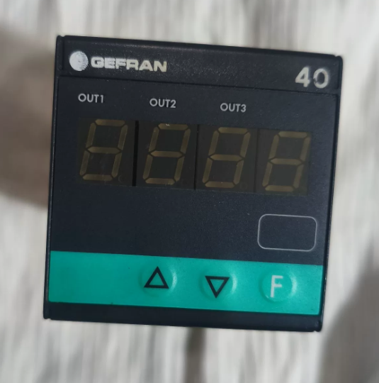
Abschluss: Ein direkter Austausch ist möglich. Die Hardware, Verkabelung und Kernfunktionen sind vollständig kompatibel. Der einzige Unterschied besteht in der Software- und Compliance-Version, die durch die letzte Ziffer angegeben wird, which will not affect normal operation. Below is the breakdown of model codes, differences and replacement guidelines.
- Digit-by-Digit Model Code Comparison (Only the last digit differs)
40T-48-4-00-RR-0-0-0-0 (Teile-Nr. F000187) vs 40T-48-4-00-RR-0-0-0-1 (Teile-Nr. F000188)
- 40T: Serie (40T48 48×48 mm Indicator / Alarm Unit)
- 48: Panel dimension: 48×48 mm (1/16 AUS)
- 4: 4-digit LED display
- 00: Stromversorgung: 100…240 V AC/DC
- RR: Ausgabe 1 & Ausgabe 2: Dual relays (5A / 250 V und)
- 0: 3rd output / Digitaler Eingang / Transmitter output: Keiner
- 0: Kommunikationsschnittstelle / 4th output: Keiner
- 0: Reserved bit
- Letzte Ziffer: 0 = Legacy software / Basisversion; 1 = Updated software / Compliance certified version (CE, UL, usw.)
- Hauptunterschiede
Identische Hardware: Terminallayout, Einbaumaße, power supply range, relay contact specifications and input types (Universal input: TC/RTD/Linear signal) are exactly the same. No wiring modification required.
Identische Funktionen: Both support 3 alarm points, on-panel/software programming and parameter password protection. The only distinction is the firmware version and compliance certification. The version ending with 1 is the updated fully compatible firmware.
Teilenummern: Model ending with 0 = F000187; Model ending with 1 = F000188.
- Ersatzempfehlungen & Notizen
- ✅ Direct replacement: Fully compatible in terms of installation, wiring and terminal definition. No rewiring needed.
- ⚠️ Mandatory operation: Reconfigure parameters (Eingabetyp, measuring range, Alarmschwelle, differential gap, usw.) after replacement. The new firmware is fully compatible with legacy parameter logic.
- Special scenario: If the original equipment requires traceability of special compliance certifications (z.B. matching UL/CE documents), verify whether strict model consistency is required on site. For general functional use, no issues will occur.
Quick Reference for Replacement: GEFAHR 40T-48-4-00-RR-0-0-0-0 / 40T-48-4-00-RR-0-0-1
- Full Model Code Explanation (Only the last digit differs)
| Codesegment | Inhalt | Beschreibung | Consistency Between Two Models |
| 1 | 40T | Produktserie: 40T Digital Alarm Controller | Völlig identisch |
| 2 | 48 | Panelgröße: 48×48 mm (1/16 Ihr Standard) | Völlig identisch |
| 3 | 4 | Anzeige: 4-digit LED Digital Tube | Völlig identisch |
| 4 | 0 | Stromversorgung: Wide voltage 100~240 V AC/DC | Völlig identisch |
| 5 | RR | Ausgabekonfiguration: Two independent relay alarm outputs | Völlig identisch |
| 6 | 0 | 3rd output / Digitaler Eingang / Transmitter output: Keiner | Völlig identisch |
| 7 | 0 | Communication port / 4th output: Keiner | Völlig identisch |
| 8 | 0 | Hardware reserved bit: Disabled reserved functions | Völlig identisch |
| 9 | 0 / 1 | Firmware & Compliance Version: | Einziger Unterschied |
| 0 = Basic firmware | |||
| 1 = Updated firmware (CE/UL certified) |
> Kernschlussfolgerung: 100% compatibility in hardware structure, electrical specifications, terminals and functional pins. Direct replacement is supported.
- Allgemeine technische Spezifikationen (Identical for both models)
| Artikel | Spezifikation |
| Montagemaß | 48×48 mm panel, standard DIN cutout |
| Operating Power | 100 ~ 240 V AC/DC, Power consumption < 3 VA |
| Measuring Input | Universeller Typ: Thermoelement (K/J/S/T), Pt100 RTD, linear voltage/current analog signal |
| Display Accuracy | ±0,2 % FS, Sampling rate: 10 Mal pro Sekunde |
| Relaisausgang (RR) | 2-channel passive normally open contacts, Kontaktbewertung: 5A / 250 V und |
| Betriebstemperatur | 0 ~ +50 ℃ |
| Schutz vor Eindringen | Frontplatte: IP65; Terminal side: IP20 |
| Spannungsfestigkeit | Withstand voltage 2000 V AC between input, Ausgang und Stromversorgung |
- Terminal Pin Definition (Universal for on-site wiring, no rewiring)
Standard terminal block on the rear of the device, gesamt 8 Terminals. Terminal layout and functions are fully identical for both models.
| Terminal-Nr. | Funktion | Verkabelungsanleitung | Bemerkungen |
| 1 | Power L / + | AC Live / DC Positive | Leistungsaufnahme |
| 2 | Power N / – | AC Neutral / DC Negative | Leistungsaufnahme |
| 3 | Measuring Input + | Sensor signal positive | Connect to thermocouple/RTD/analog output |
| 4 | Measuring Input – | Sensor signal negative | Common end of signal loop |
| 5 | Alarm Relay 1 KEIN Kontakt | 1st alarm output | Corresponds to the 1st alarm logic |
| 6 | Alarm Relay 1 Gemeinsam | Common terminal of Relay 1 | Passive contact, unpolar |
| 7 | Alarm Relay 2 KEIN Kontakt | 2nd alarm output | Corresponds to the 2nd alarm logic |
| 8 | Alarm Relay 2 Gemeinsam | Common terminal of Relay 2 | Passive contact, unpolar |
Ergänzen: This model has no transmitter output or communication port, and all terminals are fully utilized. Wire strictly in accordance with the above table.
- Panel Keys & Step-by-Step Parameter Configuration (Mandatory after replacement)
Schlüsselbeschreibung
`SET`: Menü aufrufen / Confirm parameter / Switch menu level
`▲/▼`: Wert anpassen / Switch options
`◀`: Shift digit / Return to previous menu
Complete Configuration Steps (General for field application)
Schritt 1: Enter Programming Mode
Press and hold `SET` for 3 seconds to enter parameter setting interface. For some units, enter the factory default password 0000 and press `SET` to confirm.
Schritt 2: Set Input Signal Type (Core setting)
- Locate parameter `In.Ty` (Eingabetyp)
- Use `▲/▼` to select the sensor type:
`K`: K-type Thermocouple
`Pt`: Pt100 RTD
`0-10`: 0-10V Analog Signal
`4-20`: 4-20mA Analog Signal
- Press `SET` to save and proceed to the next item.
Schritt 3: Set Measuring Range
- `Lo`: Set Lower range limit
- `Hi`: Set Upper range limit
- Adjust according to actual process range, then press `SET` to confirm.
Schritt 4: Configure Dual Alarm Relays (Corresponding to RR outputs)
- `AL1`: 1st alarm value (for Relay on Terminal 5/6)
- `dF1`: Differential gap of 1st alarm (to prevent frequent relay switching, recommended value: 0.5~2,0)
- `AL2`: 2nd alarm value (for Relay on Terminal 7/8)
- `dF2`: Differential gap of 2nd alarm
- Select alarm mode: High limit alarm / Low limit alarm as required.
Schritt 5: Parameter speichern & Ausfahrt
After all settings are completed, press `◀` repeatedly to return to the main interface. Parameters will be saved automatically.
To lock parameters against accidental modification: Locate `P.cod` and set a custom password.
- On-site Check List after Replacement (Check item by item to avoid faults)
Inspektion vor dem Einschalten
- Mechanical mounting: Secure the instrument on the panel without looseness; cutout size complies with 48×48 mm.
- Wiring check: Überprüfen Sie die Stromversorgung, sensor and relay circuits per terminal table; ensure no loose connection, wrong wiring or short circuit.
- Power confirmation: On-site power supply is 100~240 V AC/DC within rated range.
Post-power-on Inspection
- Einschalttest: 4-digit LED lights up normally, no black screen or flickering.
- Signal verification: Compare real-time reading with actual sensor value; ensure deviation is within allowable range.
- Alarm test: Simulate over-limit conditions manually; confirm two relays actuate/de-energize normally and external loads work properly.
- Parameter recheck: Keep range, alarm values and differential gap consistent with original settings.
Compliance Check (Execute as required)
General industrial sites / No certification traceability required: No extra operation needed.
Ausrüstung exportieren / Strict model & certificate consistency required: The new model ending with 1 is the certified version with complete CE/UL documents for filing.
- Häufige Fehler & Troubleshooting after Replacement
| Fehlerphänomen | Mögliche Ursachen | Lösungen |
| No display after power-on | 1. Reversed/loose power wiring | Klemmen wieder festziehen, measure input voltage and restore rated power supply |
| 2. Supply voltage out of range | ||
| Fluctuating / Inaccurate readings | 1. Poor sensor connection | Reconnect sensor cables and verify In.Ty parameter |
| 2. Wrong input type selected | ||
| Normal reading but relay no action | 1. Incorrect alarm value | Recheck AL1/AL2 thresholds and switch alarm mode |
| 2. Wrong alarm mode selected | ||
| Relay switches frequently | Excessively small differential gap | Increase dF1/dF2 value |
| Parameters reset automatically | Failed to exit menu completely / Stuck panel keys | Fully exit setting interface and clean foreign matters on keys |
- Ergänzende Hinweise
- Firmware compatibility: The updated firmware (ending with 1) is fully backward compatible with legacy parameter logic, with no function reduction or protocol mismatch.
- Spare parts procurement: Both models are interchangeable for reordering. The updated version ending with 1 is recommended for wider certification coverage.
- Long-term operation: The two models have identical service life and load capacity, and require no differentiated maintenance standards.

