

It is a multi-functional temperature control instrument.
Grundparameter
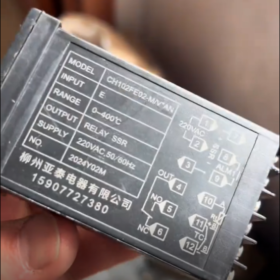
Thermocouple Type: Type K, requiring a thermocouple temperature sensing element for connection.
Output Type: Solid-state output. The output terminals provide 24V DC voltage for connecting a solid-state relay.
Genauigkeitsklasse: Klasse 0.5, with a maximum allowable deviation of ±0.5℃ for the actual temperature.
Temperature Measurement Range: Based on Type K thermocouple, the measurable range is from -200℃ to +1300℃.
Betriebsspannung: 220V und, 50Hz.
Betriebsumgebung: The temperature of the installation location ranges from 0℃ to 50℃, and the humidity ranges from 35% Zu 85%.
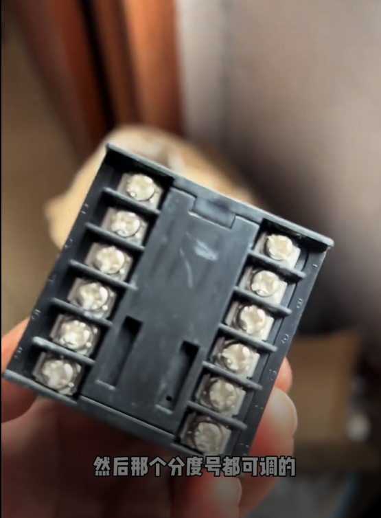
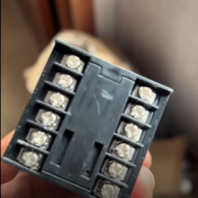
Verkabelungsmethode
Power Wiring: Terminals 1 Und 2 are connected to 220V AC power supply.
Output Wiring: Terminals 4 Und 5 are for solid-state relay output, with Terminal 4 as 24V positive and Terminal 5 as 24V negative.
Alarm Wiring: Terminals 6 Und 7 are for alarm output, which will be connected when an alarm is triggered.
Temperature Sensing Element Wiring: Since the thermocouple type is K, connect the temperature sensing element to Terminals 9 Und 10 according to the thermocouple wiring method.
Control Parameter Settings
Alarm Parameter (ALE): The alarm value can be set. The alarm will be triggered and Terminals 6 Und 7 will be connected when the actual value (PV) is greater than the sum of the set value (SV) and the alarm value.
Auto-tuning Function (ATU): Set it to 1 and press the SET key to start PID auto-tuning. The AT indicator will flash. The auto-tuning time varies from several minutes to several hours depending on on-site conditions.
P Value: A PID response time adjustment parameter. The larger the P value, the faster the response speed.
I Value: Used to eliminate steady-state errors.
D Value: Used to suppress temperature fluctuations. The larger the value, the more the advanced control quantity.
Correction Value (SC): When the temperature measurement is inaccurate, the temperature sensing element can be calibrated by modifying the SC value.
Abmessungen: The overall dimensions are 48×48×100mm, and the cutout dimensions are 45⁺⁰·⁵₀×45⁺⁰·⁵₀mm.
Parameter Setting Guide for Liuzhou Yatai Temperature Controller CH102FE02-M
The parameter setting of Liuzhou Yatai CH102FE02-M temperature controller is divided into two parts: basic temperature setting (SP) and advanced control parameter adjustment. The detailed operation steps and parameter descriptions are as follows:
- Key Function Description
| Key | Funktion |
| SET | Confirm/enter setting mode (short press); save and exit (long press for 4 Sekunden) |
| ▲ | Increase value/switch parameters |
| ▼ | Decrease value/switch parameters |
| None | Run/stop (this key may be available on some models) |
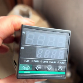
- Basic Temperature Setpoint (SP) Setting (Common Operation)
- After the instrument is powered on, it enters the standard display mode: the upper row displays PV (measured value) and the lower row displays SV (set value).
- Short press the SET key, the SV value starts to flash (enter the set value modification state).
- Press the ▲/▼ keys to adjust the SV value to the target temperature (z.B., 150℃).
- Short press the SET key again to confirm, the SV value stops flashing, and the instrument returns to the standard display mode.
III. Advanced Control Parameter Setting (Enter by Long Pressing the SET Key)
- In the standard display mode, long press the SET key for about 4 seconds until the upper row displays the parameter code (z.B., ALE) to enter the advanced setting mode.
- Press the ▲/▼ keys to switch parameter codes and find the parameter to be modified.
- Short press the SET key to enter the modification state of the parameter value, and the value flashes.
- Press the ▲/▼ keys to adjust the value to the required one.
- Short press the SET key again to confirm and save the parameter.
- Repeat steps 2–5 to set other parameters.
- After all parameters are set, long press the SET key for about 4 seconds to return to the standard display mode (parameters are saved automatically).
- Description and Setting Suggestions for Key Parameters
| Parameter Code | Parametername | Funktionsbeschreibung | Setting Range | Factory Default | Recommended Setting |
| ALE | Alarm Deviation | Terminals 6–7 are connected for alarm when PV > SV + ALE | 0–999℃ | 10℃ | Based on process requirements (z.B., 5℃) |
| ATU | Auto-tuning Function | 1 = enable auto-tuning; 0 = disable auto-tuning | 0/1 | 0 | Stellen Sie auf ein 1 for first use, set to 0 after completion |
| P | Proportional Band | The smaller the P value, the faster the response and the larger the possible overshoot | 1–999 | 20 | Automatically generated after auto-tuning |
| ICH | Integral Time | Eliminate steady-state errors; the smaller the I value, the stronger the integral effect | 1–999 | 60 | Automatically generated after auto-tuning |
| D | Derivative Time | Suppress temperature fluctuations; the larger the D value, the stronger the advanced control | 0–999 | 10 | Automatically generated after auto-tuning |
| SC | Temperature Correction | Correct temperature measurement errors (z.B., if PV displays 100℃ and the actual temperature is 102℃, set SC = +2) | -99~+99℃ | 0 | Adjust according to calibration results |
| Sn | Thermocouple Type | Input type selection (fixed as Type K for CH102FE02-M) | K/E/J, usw. | K | Do not modify |
| Ctrl | Control Mode | Fixed as PID control (characteristic of CH102FE02-M model) | PID/ON-OFF | PID | Do not modify |
- Steps for Using Auto-tuning Function (Recommended)
Auto-tuning can automatically calculate the optimal PID parameters, which is suitable for first use or when system parameters change:
- Ensure that the load is correctly connected and the instrument is in the running state.
- Set the target SV value (it is recommended to set it to 80% of the commonly used temperature).
- Enter the advanced setting mode, find the ATU parameter, and set it to 1.
- Short press the SET key to confirm, the AT indicator starts to flash, and auto-tuning is activated.
- During the auto-tuning process, the temperature will have 1–2 obvious overshoots, which is a normal phenomenon.
- Wait until the AT indicator stops flashing (about several minutes to several hours, depending on the thermal inertia of the system), auto-tuning is completed, and the PID parameters are saved automatically.
- It is recommended to set the ATU parameter to 0 (disable auto-tuning) to avoid false triggering.
- Method for Setting Temperature Correction (SC)
When the temperature measurement is inaccurate (z.B., deviation between the displayed value and the actual value):
- Use a standard thermometer to measure the actual temperature (z.B., 120℃).
- Record the PV value displayed by the instrument (z.B., 118℃).
- Calculate the correction value: SC = actual temperature PV displayed value (120-118=+2).
- Enter the advanced setting mode, find the SC parameter, and set it to the calculated value (+2).
- After confirmation and saving, the PV value will display the corrected temperature (120℃).
VII. Notizen
- Before modifying parameters: Ensure that the system is in a safe state to avoid equipment damage or safety accidents caused by incorrect parameters.
- During auto-tuning: Do not power off or stop midway, ansonsten, auto-tuning needs to be performed again.
- Sn/Ctrl parameters: CH102FE02-M is fixed as Type K input and PID control. Do not modify these parameters, ansonsten, the instrument will work abnormally.
- Alarm function: After setting the ALE parameter, ensure that Terminals 6 Und 7 are correctly connected to the alarm device.
- Parameter saving: After all parameters are modified, you must long press the SET key to return to the standard mode for automatic saving.


")


NH42-63-318x560.png "Automatische Transferschalter vom Typ CHINT PC (ATS)NH42-63/4SZ")

")

