

Product Overview
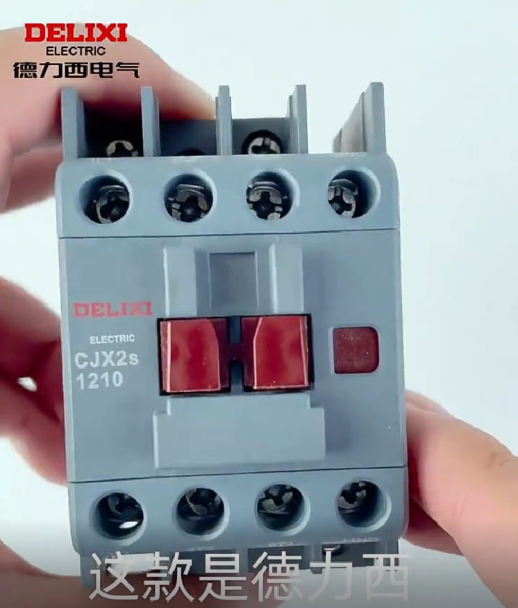
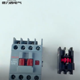
The Delixi CJX2s-1210 is a 3-pole AC contactor belonging to the Navigator Series, specially designed for motor control and protection. Adopting a new-generation technology platform, it is suitable for frequent operation scenarios under AC-3 duty (rated operating current of 12A at voltage below 400V), featuring high reliability, long service life and easy installation.
Model Explanation: CJX2s (series code) 12 (rated operating current 12A) 10 (1 normally open auxiliary contact, 0 normally closed auxiliary contacts)
Aplicación principal: It is used for starting, stopping and reversing control of three-phase asynchronous motors in industrial automation control systems. It can be combined with JRS1Dsp series thermal overload relays to realize motor overload and phase failure protection.
- Parámetros técnicos básicos (Technical Specifications)
| Categoría de parámetro | Detailed Specifications | Observaciones |
| Parámetros básicos | ||
| Número de polo | 3 polos | Rated voltage of main circuit up to 690V |
| Corriente de funcionamiento nominal (Es decir) | 12A (AC-3, 400V) | Conventional Heating Current (It): 25A |
| Tensión de funcionamiento nominal (Ue) | 400V/690V | Complies with GB 14048.4 estándar |
| Configuración de contacto auxiliar | 1NO (1 Normalmente abierto) | No built-in normally closed contacts, external expansion available |
| Parámetros de la bobina | ||
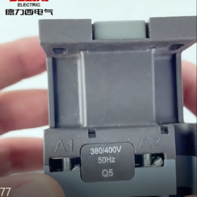
| Rated Control Voltage (Uc) | AC 220V/380V/24V/36V/110V/240V | Universal for 50/60Hz, DC coil customizable |
| Pick-up Voltage Range | 70%-120% Uc | Adapts to grid voltage fluctuations for more stable operation |
| Drop-out Voltage Range | 20%-75% Uc | Ensures reliable breaking |
| Consumo de energía de la bobina | Pick-up: aprox. 70Virginia; Holding: aprox. 7Virginia | Energy-saving design to reduce operating temperature rise |
| Performance Parameters | ||
| Tensión nominal de aislamiento (interfaz de usuario) | 800V | Clearance and creepage distance meet insulation requirements |
| Rated Impulse Withstand Voltage (Uimp) | 8kV | Strong surge resistance |
| Vida útil mecánica | ≥ 10 millones de operaciones | Upgraded silver contact technology for excellent arc resistance |
| Electrical Service Life (AC-3, 400V, 12A) | ≥ 1 millones de operaciones | 60% longer service life than industry average for frequent operations |
| Rated Operating Frequency | 1200 operations/hour | Suitable for frequent start-stop control scenarios |
| Duty | AC-3 (squirrel-cage motor starting) | Can be used for AC-1 (carga resistiva) and AC-4 (motor reversing) with derating |
| Parámetros ambientales | ||
| Temperatura de funcionamiento | -25℃ ~ +55℃ | Altitude ≤ 2000m, humedad ≤ 95% (sin condensación) |
| Clase de protección | IP20 | Prevents finger contact with live parts; must be installed inside electrical cabinets |
| Parámetros de instalación | ||
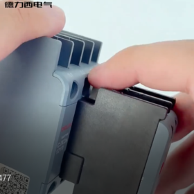
| Método de montaje | Montaje en carril DIN estándar de 35 mm / screw fixing | Minimum spacing between contactors ≥ 50mm for heat dissipation |
| Dimensiones generales | Aprox.. 50mm × 80mm × 58mm | Peso: aprox. 320gramo |
| Bloques de terminales | Circuito principal: M4 screws; Auxiliary circuit: M3 screws | Main circuit wire cross-section: 1.5-4mm²; Auxiliary circuit wire cross-section: 0.5-1.5mm² |
- Structural Features and Advantages
3.1 Core Structural Innovations
Silver Alloy Contact System: Main contacts adopt large-size silver alloy materials, which are resistant to arc erosion, reduce contact resistance, decrease temperature rise and extend service life.
Optimized Arc Extinguishing System: Extended main contact barriers increase creepage distance and improve insulation strength. Optional transparent cover is available for dusty environments.
Modular Design: Contactos auxiliares, coils and arc extinguishing covers are independent components, facilitating maintenance and replacement, and the number of auxiliary contacts can be flexibly expanded.
3.2 Performance Advantages
Amplia adaptabilidad de voltaje: The coil pick-up voltage range of 70%-120% Uc makes it suitable for industrial sites with unstable voltage.
Low Power Consumption Design: The holding power consumption is only 1/10 of the pick-up power consumption, achieving significant energy-saving effect and reducing operating costs.
Perfect Compatibility: It seamlessly matches with JRS1Dsp series thermal overload relays with matching installation dimensions, forming a complete motor protection unit.
- Application Scenarios and Selection Guide
4.1 Escenarios de aplicación típicos
Direct start and stop control of three-phase asynchronous motors (≤ 5.5kW, 400V)
Electrical control systems of general machinery such as fans, bombas de agua, compressors and conveyors
Power control circuits of industrial automation production lines, machine tools and packaging machinery
Control of non-inductive loads such as lighting and resistance furnaces (rated current can be increased to 25A under AC-1 duty)
4.2 Selection Key Points
Coincidencia de carga: Motor power ≤ 5.5kW (400V), rated current ≤ 12A; avoid overload operation.
Frecuencia de funcionamiento: For frequent start-stop (≥ 600 operations/hour), derating by 10%-20% is recommended.
Control Voltage: Select appropriate coil voltage according to the control system power supply (AC 220V is the most commonly used).
Protection Matching: Must be used with thermal overload relays (p.ej., JRS1Dsp-25) to achieve overload and phase failure protection.
Condiciones ambientales: Additional protective measures shall be taken in high-temperature, high-humidity and dusty environments, or products with higher protection classes shall be selected.
- Installation and Maintenance Specifications
5.1 Pasos de instalación (Professional Operation Procedure)
- Preparación previa a la instalación
Check that the product model and specifications are consistent with the order, the appearance is intact and accessories are complete.
Verify that the coil voltage matches the control circuit power supply, and perform insulation test (500V megger, insulation resistance ≥ 10MΩ).
Ensure that the installation environment meets the requirements (temperatura, humedad, sin gas corrosivo).
- Installation Operation
Install on standard 35mm DIN rail or fix on flat metal plate with M4 screws.
Cableado del circuito principal: Connect three-phase power supplies L1, L2, L3 to the input terminals of the contactor main contacts, and connect the output terminals to the motor stator windings.
Cableado del circuito de control: Connect coil terminals A1 and A2 to the control power supply; auxiliary contacts are used for self-locking, interlocking or signal indication.
Terminal block tightening torque: Main circuit ≥ 2.5N·m, auxiliary circuit ≥ 1.2N·m to avoid heating caused by loose connections.
- Notas de instalación
The spacing between contactors and between contactors and other components shall be ≥ 50mm to ensure good heat dissipation.
Install vertically (coil facing upwards); avoid horizontal or inverted installation which may affect performance.
It is recommended to connect a 2A fuse in series in the control circuit to protect the coil from overload damage.
5.2 Mantenimiento (Inspección periódica)
| Maintenance Item | Inspection Cycle | Inspection Content | Treatment Measures |
| Inspección visual | Once a month | Check for no cracks or deformation on the shell, no loose or overheated traces on terminal blocks | Tighten loose terminals and replace damaged parts |
| Inspección de contacto | Once a quarter | Check for no severe ablation or oxidation on the surface of main contacts, and ensure flexible operation of auxiliary contacts | Slight ablation can be polished; replace contact components if severely damaged |
| Coil Inspection | Once every six months | Check for no overheating, discoloration or peculiar smell of the coil, insulation resistance ≥ 10MΩ | Replace aging or damaged coils |
| Arc Extinguishing System Inspection | Once a year | Check that the arc extinguishing cover is clean without scaling and damage | Clean the arc extinguishing cover and replace damaged parts |
Safety Warning: Installation and maintenance must be performed by professional electricians. Live operation is strictly prohibited. Disconnect the upper-level power supply and verify no voltage before operation.
- Common Fault Troubleshooting and Solutions
| Fenómeno de falla | Posibles causas | Pasos para solucionar problemas | Soluciones |
| Contactor fails to pick up | 1. No voltage on the coil | 1. Measure the voltage at coil terminals A1/A2 to confirm normal control power supply | 1. Repair open circuits in the control circuit |
| 2. Coil damage | 2. Check coil resistance (aprox. several hundred ohms normally) | 2. Replace the coil | |
| 3. Atasco mecánico | 3. Manually operate the mechanism to check flexibility | 3. Clean and lubricate the mechanism, replace damaged parts | |
| Loud buzzing/chattering noise after pick-up | 1. Low power supply voltage (below 70% of rated coil voltage) | 1. Measure the coil voltage to check if it is ≥ 70% Uc | 1. Adjust the power supply voltage to the rated range |
| 2. Oil/dust on the iron core end faces leading to incomplete pick-up | 2. Check the cleanliness of the iron core contact surfaces | 2. Disconnect the power supply, desmontar el contactor, and clean the moving and static end faces of the iron core with alcohol to remove oil and dust | |
| 3. Broken short-circuit ring of the iron core (unique to AC contactors) | 3. Observe if there is obvious wear on the iron core | 3. Replace the broken short-circuit ring (core disassembly required; core assembly replacement is recommended) | |
| 4. Iron core jamming resulting in incomplete pick-up | 4. Check the mechanical transmission components, remove foreign objects, y aplique una pequeña cantidad de grasa lubricante | ||
| Severe contact ablation | 1. Overload current exceeding the rated current of the contactor (12A) | 1. Verify the load current against the rated current of the contactor | 1. Replace with a contactor of larger capacity (p.ej., CJX2s-1810) in case of overload |
| 2. Excessively high operating frequency (over 1200 operations/hour) | 2. Check if the actual operating frequency exceeds the specification | 2. Reduce the operating frequency or select a special high-frequency contactor | |
| 3. Mismatched load type (p.ej., AC-4 duty without derating) | 3. Check if the arc extinguishing cover is damaged | 3. Derate by 50% for AC-4 (motor reversing) escenarios; appropriately increase the current for non-inductive loads | |
| 4. Damaged/missing arc extinguishing cover leading to ineffective arc extinguishing | 4. Replace the damaged arc extinguishing cover and ensure proper installation | ||
| Coil overheating and burning with burnt smell | 1. Excessively high coil voltage (over 120% of rated voltage) | 1. Measure the coil voltage to check if it is ≤ 120% Uc | 1. Replace with a coil of matching voltage and install a voltage stabilizer |
| 2. Continuous coil energization (defective control circuit design without power-off loop) | 2. Check if there is self-locking failure in the control circuit | 2. Optimize the control circuit by adding a power-off switch or time relay to avoid continuous coil energization | |
| 3. Excessively high ambient temperature/insufficient installation spacing leading to poor heat dissipation | 3. Check the ventilation condition of the installation environment | 3. Ensure that the contactor installation spacing is ≥ 50mm and improve the ventilation condition of the electrical cabinet | |
| 4. Iron core jamming causing continuous high-current coil pick-up | 4. Troubleshoot the cause of mechanical jamming before putting it into use again |
- Accessories and Expansion Functions
7.1 Accesorios estándar
35mm DIN rail mounting clips (standard configuration)
Transparent dust cover (opcional, suitable for dusty environments)
Auxiliary contact expansion module (can add 1NO+1NC, model: F4-11)
7.2 Combined Applications
Combined with JRS1Dsp-25 thermal overload relay to realize motor overload, phase failure and locked-rotor protection
Cooperated with JZC4s contactor relay to expand the contact capacity of the control circuit
Can be equipped with a pneumatic time delay head (p.ej., ST4P) to realize time-delay control functions such as motor star-delta starting
- Certifications and Quality Assurance
Certificaciones: CCC, CE, RoHS and other authoritative certifications; complies with GB 14048.4 y CEI 60947-4-1 estándares
Seguro de calidad: Delixi Electric provides 18-month product warranty; free repair or replacement for non-human damage within the warranty period
Production Standards: Manufactured on automated production lines with 100% factory inspection to ensure product consistency and reliability
- Ordering Information
| Modelo | Voltaje de la bobina | Order Number Example | Observaciones |
| CJX2s-1210 | CA 220 V | CJX2S1210M7 | Universal for 50/60Hz, RoHS compliant |
| CJX2s-1210 | CA 380V | CJX2S1210Q7 | Suitable for industrial 380V control circuits |
| CJX2s-1210 | AC 24V | CJX2S1210E | Safe voltage control, suitable for humid environments |
Nota: For DC coil or special configurations, please contact Delixi Electric technical support for customization.
Common Faults and Solutions of Delixi CJX2s-1210 AC Contactor
Faults of the Delixi CJX2s-1210 contactor are mainly concentrated in three categories: electromagnetic system, contact system and mechanical structure. The following lists the causes and corresponding solutions classified by fault phenomena, considering both on-site quick troubleshooting and long-term maintenance requirements:
| Fault Category | Fenómeno de falla | Common Causes | Soluciones |
| Electromagnetic System Faults | 1. Contactor fails to pick up, no coil action | 1. Control circuit power-off/fuse blown | 1. Measure the voltage at coil terminals A1/A2 with a multimeter to confirm normal control power supply; replace the blown fuse |
| 2. Disconnects immediately after power-off (no self-locking) | 2. Mismatched coil voltage and power supply voltage (p.ej., AC220V coil connected to 380V) | 2. Verify the rated coil voltage (p.ej., CJX2s-1210M7 is AC220V) and replace with a matching coil | |
| 3. Loose/oxidized coil terminal wiring | 3. Apriete los bloques de terminales, polish the oxidized contacts with sandpaper and apply conductive paste | ||
| 4. Burnt coil (internal open circuit/short circuit) | 4. Measure the coil resistance (normally several hundred ohms; replace the coil if open circuit/short circuit occurs) | ||
| 5. Poor contact of auxiliary contacts in the self-locking loop | 5. Check the 1NO auxiliary contacts, clean the contact surfaces or replace the auxiliary contact module | ||
| Loud buzzing/chattering noise from the iron core after pick-up | 1. Low power supply voltage (below 70% of rated coil voltage) | 1. Adjust the power supply voltage to the rated range (70%-120% Uc) | |
| 2. Oil/dust on the iron core end faces leading to incomplete pick-up | 2. Disconnect the power supply, desmontar el contactor, and clean the moving and static end faces of the iron core with alcohol to remove oil and dust | ||
| 3. Broken short-circuit ring of the iron core | 3. Replace the broken short-circuit ring (core disassembly required; core assembly replacement is recommended) | ||
| 4. Check the mechanical transmission components, remove foreign objects, y aplique una pequeña cantidad de grasa lubricante | |||
| Coil overheating and burning with burnt smell | 1. Excessively high coil voltage (over 120% of rated voltage) | 1. Replace with a coil of matching voltage and install a voltage stabilizer | |
| 2. Continuous coil energization (defective control circuit design without power-off loop) | 2. Optimize the control circuit by adding a power-off switch or time relay to avoid continuous coil energization | ||
| 3. Excessively high ambient temperature/insufficient installation spacing leading to poor heat dissipation | 3. Ensure that the contactor installation spacing is ≥ 50mm and improve the ventilation condition of the electrical cabinet | ||
| 4. Iron core jamming causing continuous high-current coil pick-up | 4. Troubleshoot the cause of mechanical jamming before putting it into use again | ||
| Contact System Faults | Severe ablation of main contacts with blackening and arcing on the surface | 1. Overload current exceeding the rated current of the contactor (12A) | 1. Verify the load power (≤ 5.5kW at 400V); replace with a contactor of larger capacity (p.ej., CJX2s-1810) in case of overload |
| 2. Excessively high operating frequency (over 1200 operations/hour) | 2. Reduce the operating frequency or select a special high-frequency contactor | ||
| 3. Mismatched load type (p.ej., AC-4 duty without derating) | 3. Derate by 50% for AC-4 (motor reversing) escenarios; appropriately increase the current for non-inductive loads | ||
| 4. Damaged/missing arc extinguishing cover leading to ineffective arc extinguishing | 4. Replace the damaged arc extinguishing cover and ensure proper installation | ||
| Main contact welding (unable to disconnect after pick-up) | 1. Load short circuit causing instantaneous high-current impact on contacts | 1. Troubleshoot the load-side short-circuit fault (p.ej., cortocircuito del devanado del motor), repair and replace the contactor | |
| 2. Long-term contact ablation leading to excessive contact resistance and heating welding | 2. Regularly inspect the contact status; slight ablation can be polished with fine sandpaper; replace contact components or the whole machine if severely damaged | ||
| 3. Excessively high voltage during contactor breaking leading to ineffective arc extinguishing | 3. Install RC absorbers or surge suppressors when breaking inductive loads | ||
| Auxiliary contact failure (self-locking/signal circuit disconnection) | 1. Oxidized/dusty auxiliary contacts leading to poor contact | 1. Clean the surfaces of auxiliary contacts or replace the auxiliary contact module (F4-11 module can be expanded) | |
| 2. Auxiliary contact current overload (exceeding the rated current of 5A) | 2. Auxiliary contacts are only used for control circuits; avoid directly carrying high-power loads | ||
| 3. Loose contact wiring | 3. Tighten the M3 terminal blocks with torque ≥ 1.2N·m | ||
| Mechanical Structure Faults | Sticking or unsmooth pick-up/disconnection action of the contactor | 1. Dust or foreign objects entering the shell and jamming the transmission mechanism | 1. Disconnect the power supply, desmontar el contactor, clean internal foreign objects and keep the mechanism clean |
| 2. Fatigue or breakage of the moving iron core return spring | 2. Replace the fatigued or broken return spring | ||
| 3. Inclined installation of the contactor leading to uneven stress on the iron core | 3. Ensure vertical installation of the contactor (coil facing upwards) with flat rail or screw mounting | ||
| Slow reset of moving contacts after contactor disconnection | 1. Insufficient elasticity of the return spring | 1. Replace the return spring | |
| 2. Oil adhesion on the iron core end faces causing magnetic hysteresis | 2. Clean the iron core end faces to remove oil | ||
| 3. Failure of the contact pressure spring | 3. Adjust or replace the contact pressure spring |
General On-site Troubleshooting Steps (Seguridad ante todo)
- Power-off and Voltage Verification: Disconnect the upper-level power supply of the contactor before troubleshooting, and verify no voltage with a voltage tester to avoid electric shock.
- Inspección visual: Observe whether the contactor shell is damaged, el cableado está suelto, the contacts are ablated, and the coil is discolored.
- Multimeter Testing:
Measure coil resistance: Determine if the coil has an open circuit/short circuit.
Measure contact on-off status: Main contacts should be on when picked up and off when disconnected.
- Mechanical Testing: Manually press the moving iron core to test the smoothness of pick-up/reset and determine if there is jamming.
Recomendaciones de mantenimiento preventivo
- Limpieza periódica: Clean dust and oil inside the contactor once a quarter, focusing on the iron core end faces and contact surfaces.
- Inspección de cableado: Tighten the terminal blocks once a month; the torque of main circuit M4 terminals is ≥ 2.5N·m, and that of auxiliary circuit M3 terminals is ≥ 1.2N·m.
- Contact Maintenance: When the contact ablation area exceeds 1/3, replace the contact components or the whole machine in time to avoid fault expansion.
- Protección ambiental: Install a transparent dust cover in dusty and humid environments, or select products with higher protection classes.


")


NH42-63-318x560.png "Interruptores de transferencia automática tipo PC CHINT (ATS)NH42-63/4SZ")

")

