


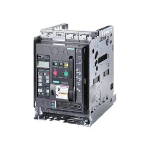
1.In-depth Model Breakdown (3WT2M40 ETU35WT F-4P)
| Segmento de modelo | Descripción | Detailed Explanation |
| 3WT | Serie de productos | Siemens SENTRON series air circuit breaker, rated current ranging from 400A to 4000A, breaking capacity up to 66kA |
| 2 | Size Specification | Tamaño 2, rated current range from 1000A to 2000A |
| M40 | Corriente nominal | M40 indicates rated current In = 1600A (M40 corresponds to 1600A, M32 = 1250A, M50 = 2000A) |
| ETU35WT | Unidad de disparo electrónico | Basic three-stage protection trip unit (LSI), equipped with standard LCD Chinese display, providing overload long-time delay, short-circuit short-time delay and instantaneous short-circuit protection functions |
| F | Mounting Type | F = Fixed mounting (W = Withdrawable/draw-out mounting) |
| 4PAG | Número de polo | Four-pole (3P = Three-pole), suitable for three-phase four-wire systems requiring neutral protection |
- Core Technical Parameter Table
2.1 Parámetros eléctricos básicos
| Parámetro | Valor | Estándar |
| Rated Operational Voltage (Ue) | 500V/690V AC 50/60Hz | CEI 60947-2 |
| Corriente nominal (En) | 1600A | CEI 60947-2 |
| Rated Short-circuit Breaking Capacity (uci) | 66el (500V) / 55el (690V) | CEI 60947-2 |
| Rated Short-time Withstand Current (Icw) | 66kA/1s (500V) | CEI 60947-2 |
| Tensión nominal de aislamiento (interfaz de usuario) | 1000V y | CEI 60947-2 |
| Rated Operational Frequency | 50/60Hz | CEI 60947-2 |
| Número de polo | 4-polo (3 polos + neutral pole) | CEI 60947-2 |
| Mounting Type | Fijado | CEI 60947-2 |
2.2 ETU35WT Trip Unit Protection Parameters
| Función de protección | Setting Range | Time Characteristic | Descripción de la función |
| Overload Long-time Delay (LT/L) | Ir = 0.4~1.0×In (640A~1600A) | Inverse time-lag, Cumple con IEC 60947-2 estándar, configurable I²t characteristic | Prevent motors and cables from overheating and burning due to long-term overload |
| Short-circuit Short-time Delay (ST/S) | Isd = 1.5~10×Ir, default 3×Ir | Definite time-lag, adjustable from 0.1s to 0.5s | Achieve selective protection, isolate fault areas, and avoid overall system power outage |
| Instantaneous Short-circuit (INST/I) | Ii = 5~15×In, default 10×In | No time delay, operation time ≤ 0.02s | Quickly cut off severe short-circuit faults to protect equipment from overcurrent impact |
| Trip Indication | Mecánico + electronic dual indication | – | Intuitively display trip causes (overload/short-circuit/instantaneous) |
| Memory Function | Trip cause storage ≥ 2 días (trip after activation ≥ 20 minutos) | – | Facilitate fault analysis and troubleshooting |
2.3 Parámetros mecánicos y ambientales
| Parámetro | Valor |
| Vida útil mecánica | ≥ 10,000 operaciones (operación sin carga) |
| Electrical Service Life | ≥ 1,000 operaciones (at rated current) |
| Operating Mechanism | Manual spring-charging type, with closing/tripping buttons |
| Clase de protección | IP30 (when installed inside the cabinet) |
| Temperatura de funcionamiento | -5°C~+40°C (sin reducción), -25°C~+55°C (derating required) |
| Humedad relativa | 5%~95% (non-condensing) |
| Altitud | ≤ 2000m (sin reducción), derating required for > 2000metro |
| Peso | Approximately 45kg (fixed type 4P) |
- Working Principle and Protection Mechanism
3.1 Core Working Principle
- Normal Operation: When the circuit breaker is closed, the main contacts connect the circuit, current flows through the main circuit and the trip unit sampling circuit, and the ETU35WT monitors the three-phase current in real time.
- Fault Detection: Cuando la corriente excede el valor establecido, the ETU35WT calculates the trip time according to the protection characteristic curve.
- Trip Action: When the trip condition is met, the ETU35WT sends a trip signal to drive the electromagnetic tripping mechanism to operate and quickly open the main contacts.
- Arc Extinguishing Process: The arc generated when the main contacts are opened is quickly extinguished by the arc extinguishing chamber, preventing arc reignition and phase-to-phase short circuit.
3.2 Detailed Explanation of Three-stage Protection Functions (ETU35WT LSI)
3.2.1 Overload Long-time Delay Protection (LT/L)
Principio: Based on the inverse time-lag characteristic (heat accumulation principle), the higher the current, the shorter the trip time (following the I²t law)
Solicitud: Protect cables and motors from long-term overload damage, and withstand short-term overcurrent during motor startup
Setting: Ir = 0.4~1.0×In, usually set to the rated current of the protected equipment
3.2.2 Short-circuit Short-time Delay Protection (ST/S)
Principio: Definite time-lag characteristic, set a fixed trip time (0.1s~0.5s) to achieve selective protection
Solicitud: Remain closed before the lower-level circuit breaker operates, only cut off the fault branch, and improve power supply continuity
Setting: Isd = 1.5~10×Ir, usually set to 5~8×Ir, with the time coordinated with the lower-level circuit breaker
3.2.3 Instantaneous Short-circuit Protection (INST/I)
Principio: No time-lag characteristic, trip immediately when the current exceeds the set value (≤ 0.02s)
Solicitud: Protect the circuit breaker itself and upper-level equipment from damage caused by huge short-circuit current (usually ≥ 10×In)
Setting: Ii = 5~15×In, usually set to 10~12×In to avoid the peak current during motor startup
3.3 Special Significance of 4-pole Protection
Suitable for TN-S and TN-C-S systems, providing overcurrent protection for the neutral line (N line)
When three-phase unbalance or single-phase ground fault occurs, the neutral line current may reach the phase current level, and the 4-pole design can effectively cut off the fault current
Comply with the protection requirements of IEC 60364 standard for three-phase four-wire systems
- Guía de instalación y cableado
4.1 Installation Preparation
- Safety Requirements: The power supply must be cut off and locked before installation to prevent electric shock
- Cabinet Requirements: Reserve sufficient installation space (width × depth × height: approximately 600mm × 800mm × 1000mm)
- Método de fijación: Fix on the distribution cabinet mounting beam with M12 bolts, torque 70N·m
4.2 Cableado del circuito principal (4PAG)
| Terminal | Purpose | Cable Specification | Torque |
| L1/L2/L3 | Three-phase power input | 4×(120mm²~185mm²) copper cable | 120Nuevo Méjico |
| norte | Neutral line input | 120mm²~185mm² copper cable | 120Nuevo Méjico |
| T1/T2/T3 | Three-phase load output | 4×(120mm²~185mm²) copper cable | 120Nuevo Méjico |
| TN | Neutral line output | 120mm²~185mm² copper cable | 120Nuevo Méjico |
4.3 Cableado del circuito de control
Auxiliary Power Supply: AC/DC 220V (operating power supply for ETU35WT)
Contactos auxiliares: 2 conjuntos de normalmente abiertos (NO) + 2 conjuntos de normalmente cerrados (CAROLINA DEL NORTE), rated current 5A/250V AC
Trip Signal: Normally closed contact (opened when tripped) for remote alarm
Control Buttons: Closing button (green), tripping button (red), need to be connected to 24V DC or 220V AC control power supply
- ETU35WT Trip Unit Setting Steps
- Enter Setting Mode: Presione el “Setting” button on the ETU panel and enter the password (por defecto 0000)
- Overload Long-time Delay (Y): Set to the rated current of the protected equipment (p.ej., if motor In = 1600A, set Ir = 1600A)
- Short-circuit Short-time Delay (Isd): Set to 5~8×Ir (p.ej., Isd = 8×1600 = 12800A), time 0.2s
- Instantaneous Short-circuit (yo): Set to 10~12×In (p.ej., Ii = 10×1600 = 16000A)
- Save Parameters: Presione el “Confirm” button to save, the ETU will automatically exit the setting mode
- Prueba de funcionamiento: Perform simulated overload and short-circuit tests to verify the correctness of the trip action
- Fault Diagnosis and Maintenance Guide
6.1 Common Fault Troubleshooting Table
| Fenómeno de falla | Posibles causas | Soluciones |
| Unable to Close | 1. Undervoltage trip unit not powered on | 1. Check the control power supply |
| 2. Trip unit failure | 2. Replace ETU35WT | |
| 3. Mechanical interlock not released | 3. Release the interlock device | |
| Unintentional Trip | 1. Setting current too small | 1. Reset the protection parameters |
| 2. Three-phase current unbalance | 2. Check load balance | |
| 3. Temperatura ambiente excesivamente alta | 3. Improve ventilation and heat dissipation | |
| No Trip During Overload | 1. Setting current too large | 1. Adjust Ir to an appropriate value |
| 2. ETU sampling circuit failure | 2. Check the current transformer | |
| 3. Tripping mechanism jamming | 3. Clean and lubricate the mechanism | |
| No Trip During Short-circuit | 1. Instantaneous setting value too large | 1. Reduce the Ii setting value |
| 2. Electromagnetic trip unit failure | 2. Replace the trip unit coil | |
| 3. Arc extinguishing chamber damage | 3. Replace the arc extinguishing chamber |
6.2 Maintenance Cycle and Content
| Ciclo de mantenimiento | Contenido de mantenimiento | Operation Points |
| Mensual | Inspección visual | Check for overheating marks, loose connections and abnormal noise |
| Trimestral | Limpieza y mantenimiento | Clean the arc extinguishing chamber and contacts with dry compressed air after power off |
| Annually | Prueba de funcionamiento | Perform simulated overload and short-circuit tests to verify protection functions |
| Every 2 Years | Mechanical Inspection | Check the operating mechanism and contact wear, replace if necessary |
| Every 5 Years | Comprehensive Overhaul | Replace aging components and recalibrate trip unit parameters |
- Escenarios de selección y aplicación
7.1 Escenarios aplicables
- Industrial Plants: Three-phase four-wire power distribution systems requiring neutral line protection
- Centros de datos: Power supply for critical loads, requiring high reliability and selective protection
- Edificios Comerciales: Power supply for large equipment such as central air conditioners and water pumps
- New Energy Field: Output side protection of photovoltaic inverters and energy storage systems
7.2 Puntos de selección
- Corriente nominal: Select according to the calculated load current (In ≥ 1.25×calculated load current)
- Capacidad de ruptura: Select according to the system short-circuit current (Icu ≥ maximum system short-circuit current)
- Selección del número de polo: Select 3P for three-phase three-wire systems, 4P for three-phase four-wire systems
- Mounting Type: Select F for fixed mounting, select W (withdrawable) for online maintenance requirements
- Trip Unit Selection:
Select ETU35WT (LSI) for basic protection
Select ETU37WT (LSIG) for ground fault protection requirements
Select ETU45WT (with communication function) for advanced applications
- Recommended Accessories and Ordering Information
| Accessory Name | Modelo | Descripción de la función |
| Contacto auxiliar | LZN102 | Agregar 2 normalmente abierto y 2 normally closed contacts for remote control |
| Undervoltage Trip Unit | LZN201 | Automatically trip when voltage loss occurs to protect equipment safety |
| Shunt Trip Unit | LZN301 | Remote trip control for emergency shutdown |
| Closing Coil | LZN401 | Electric closing device, suitable for automation systems |
| Communication Module | COM16 | Modbus RTU communication for remote monitoring |
Ordering Model: 3WT2M40 ETU35WT F-4P
Alternative Model: Withdrawable version 3WT2M40 ETU35WT W-4P
Siemens SENTRON 3WT series air circuit breaker inherits German manufacturing technology, provides reliable power distribution protection solutions, is widely used in various industrial and commercial fields, and is an ideal choice to ensure power supply continuity and equipment safety.


")


NH42-63-318x560.png "Interruptores de transferencia automática tipo PC CHINT (ATS)NH42-63/4SZ")

")

