
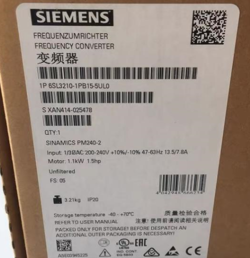

The 6SL3210-1PB15-5UL0 is a power module of the Siemens SINAMICS G120 series. Below is its key information:
Parámetros básicosSiemens 6SL3210-1KE18-8UF1
Suitable Motor Power:
– Heavy overload: 0.75 kilovatios (200% sobrecarga para 3 s, 150% sobrecarga para 57 s, 100% sobrecarga para 240 s; temperatura ambiente: -10°C a +50°C).
– Light overload: 1.1 kilovatios (150% sobrecarga para 3 s, 110% sobrecarga para 57 s, 100% sobrecarga para 240 s; temperatura ambiente: -10°C a +40°C). Siemens model number 6SL3210-1KE23-2UF1
Power Supply Voltage: 200–240 V ±10%, frequency 47–63 Hz, 1AC/3AC (single-phase input/three-phase output or three-phase input/three-phase output; specific descriptions may vary slightly due to data differences. Generalmente, three-phase input/output is the mainstream understanding. Aquí, the module supports three-phase input/output as a common scenario, and the broad description of 1AC/3AC in some materials covers input/output possibilities in different application scenarios, with three-phase being the primary application). Siemens S7-1200 series PLC
Corriente nominal: 6 A.
Clase de protección: IP20.
DimensionesSiemens 6ES7253-1AA22-0XA0 (EM253)
– Some data show 291x100x165 (height x width x depth) milímetros (FSB size).
– Other descriptions include 114.00×185.00×365.00 milímetros (differences may exist due to measurement methods or different versions; the former is used as the common description for the module’s own dimensions, while the latter may include packaging or size definitions under different specifications).
Peso: 2.9 KG.
Características del productoSiemens 6ES7235-0KD22-0XA0
– Belongs to the PM240-2 series, with no built-in filter and an integrated brake chopper.
– Control mode: integrated fieldbus; communication supports PROFINET-PN.
Ámbito de aplicación
Suitable for industrial automation control, it can drive various types of motors and is commonly used in scenarios such as drive control for fans, zapatillas, compresores, etc.. (specific applications need to be combined with actual system configurations and equipment requirements).
Installation and Wiring Guide for Siemens 6SL3210-1PB15-5UL0 Power Module
- Installation GuideSiemens 6ES7231-5QA30-0XB0 module
- Installation Environment Requirements
Temperatura ambiente: -10°C a +50°C (light overload) or +40°C (heavy overload); derating is required above 40°C.
Humedad: ≤95% relative humidity, sin condensación.
Altitud: ≤1000 m (derating is required for higher altitudes). 6ES7142-5AF00-0BA0 Siemens
Clase de protección: Only suitable for control cabinets with IP20 protection.
Installation Position: Install vertically, leaving at least 100 mm of heat dissipation space on all sides.
- Pasos de instalación mecánica
- Montaje en riel: Fix the bottom slot of the module using a DIN rail (TS35/7.5 or TS35/15).
- Fijación por tornillo: Tighten with M4 screws through the mounting holes on the top of the module (esfuerzo de torsión: 0.8–1.0 Nm).
- Module Arrangement: When paralleling multiple units, the spacing between adjacent modules should be ≥25 mm (vertical direction) or ≥100 mm (horizontal direction).
- Métodos de cableado
- Power Supply Wiring (L1/L2/L3)
Voltaje de entrada: 200–240 V AC, trifásico (or single-phase input; refer to the manual for details).
Cable Specification: It is recommended to use 2.5–6 mm² stranded copper wires (selected according to the load current).
Pasos de cableado:
- Remove the terminal cover (located on the front of the module).
- Connect the power supply cables to the L1, L2, L3 terminals (no polarity requirement).
- Tighten the terminal screws (esfuerzo de torsión: 1.2–1.5 Nm).
- Motor Wiring (UV/V/W)
Cable Specification: It is recommended to use 2.5–6 mm² stranded copper wires (needs to match the power supply cables).
Pasos de cableado:
- Connect to the U, V, W terminals (corresponding to the three-phase windings of the motor).
- Ensure the motor matches the module’s power (0.75–1.1 kW).
- Brake Resistor Wiring (+/-)
Brake Resistor Requirements: An external brake resistor is required (recommended value: 200Ω/500W).
Pasos de cableado:
- Connect the brake resistor to the + and DB terminals (the module has a built-in brake chopper).
- If no braking function is needed, short-circuit the + and DB terminals.
- Cableado del circuito de control
Entradas digitales (DE): 6 entradas digitales (support PNP/NPN), default voltage 24V DC.
Entrada analógica (AI): 1 analog input (0–10V or 0–20mA, requires jumper settings).
Salidas digitales (HACER): 2 relay outputs (rating: 2CA/250 VCA).
Salida analógica (HACIA): 1 salida analógica (0–20mA).
Wiring Key Points:
– Lay control cables separately from power cables to avoid interference.
– Use shielded cables with the shield grounded at one end.
- PROFINET Communication Wiring
Interface: Integrated RJ45 interface (X1).
Topology: Supports linear, star, or ring topologies.
Pasos de cableado:
- Use CAT5e or higher Ethernet cables to connect to a PLC or switch.
- Termination resistor setting: Only activate the termination resistor for the last device in the network (set via a switch on the module).
III. Precauciones de seguridad
- Power-Off Operation: Disconnect the main power supply and wait for at least 5 minutos (for capacitor discharge) before wiring.
- Requisitos de conexión a tierra: The module’s casing must be reliably grounded (ground resistance ≤10Ω).
- Polarity Check: Ensure correct polarity for power supply and brake resistor wiring.
- EMC Compliance: Use shielded power cables and follow Siemens’ EMC installation guidelines.
- Commissioning Recommendations
- Configuración de parámetros: Set basic parameters via STARTER or the SINAMICS G120C operation panel (p.ej., P0003=3 to activate expert-level parameters).
- Motor Identification: Perform quick commissioning (P0010=1) and automatic motor identification (P1910=1).
- Operation Test: Run (no-load) first, and only apply load after confirming correct direction and parameters.
For more detailed steps, refer to the Siemens official document 6SL3210-1PB15-5UL0 Operation Manual (document number: A5E30077851).


")


NH42-63-318x560.png "Interruptores de transferencia automática tipo PC CHINT (ATS)NH42-63/4SZ")

")

