

- Positionnement du produit et paramètres de base
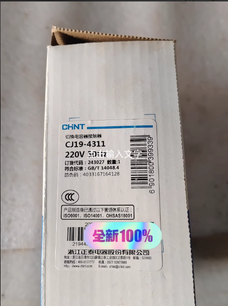
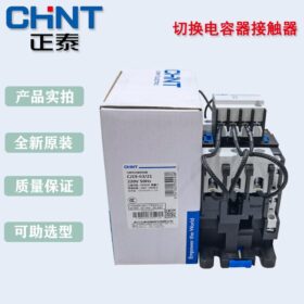
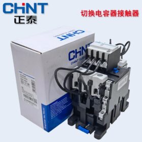
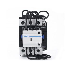
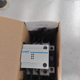
Positionnement du produit: Le CJ19-4311 est un condensateur à commutation contacteur appartenant à la série CJ19 de Chint. Conçu exclusivement pour les systèmes de compensation de puissance réactive basse tension, il est utilisé pour commuter les batteries de condensateurs shunt et améliorer le facteur de puissance.
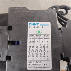
Interprétation du modèle:
CJ19: Série de contacteurs à commutation de condensateur
43: Code de spécification de base (courant nominal 43A)
11: Configuration des contacts auxiliaires (1 normalement ouvert + 1 normalement fermé)
Paramètres de base:
| Paramètre | Valeur |
| Tension nominale | C.A. 380 V/690 V |
| Courant nominal | 43UN |
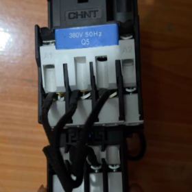
| Tension de bobine | 220V/380V (modèle standard) |
| Numéro du pôle de contact principal | 3P. |
| Contacts auxiliaires | 1NON+1NC |
| Durée de vie mécanique | 1,000,000 opérations |
| Durée de vie électrique | 100,000 opérations |
| Classe de protection | IP10 |
| Normes de conformité | GB/T 14048.4, CEI/EN 60947-4-1 |
- Structure de base et principe de fonctionnement
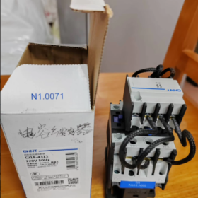
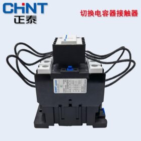
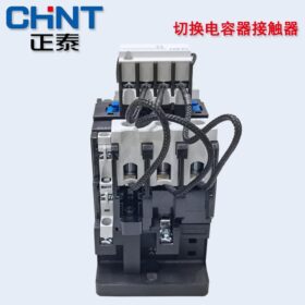
- Caractéristiques structurelles
3-Système de contact principal de pôle: Contrôle l'activation/désactivation des batteries de condensateurs
Dispositif de suppression de courant d'appel: Composant central composé de résistances de limitation de courant et d'un système de contact spécial
Contacts auxiliaires: Fournir un retour d'état pour les circuits de contrôle
Structure à double coupure à action directe: Fonctionnement flexible et forte capacité de coupure
Protection des bornes isolées: Assure la sécurité de fonctionnement
- Principe de fonctionnement
Fonction principale: Réduit le courant d'appel de fermeture (qui peut atteindre 10-20 fois le courant nominal) lorsque les condensateurs sont allumés, protéger les condensateurs et l'ensemble du système.
Séquence de travail:
Mécanisme détaillé:
① Processus de clôture:
L'excitation de la bobine génère un champ magnétique qui attire l'armature.
Phase 1: Contacts limiteurs de courant (avec aimants permanents) fermer d'abord, et le courant précharge les condensateurs via des résistances de limitation de courant.
Phase 2: Après plusieurs millisecondes (environ 8 ms), les principaux contacts se ferment, court-circuiter les résistances de limitation de courant.
Phase 3: L'aimant permanent dans les contacts limiteurs de courant est libéré par l'action du ressort, ouvrir la branche de limitation de courant.
Étape finale: Les condensateurs sont directement alimentés par les contacts principaux, effectuer une mise en marche en douceur.
② Processus d'ouverture:
La bobine est hors tension, le ressort se réinitialise, et les principaux contacts s'ouvrent en premier.
Le système auxiliaire d’extinction d’arc supprime les surtensions de commutation, protéger les condensateurs et le circuit.
III. Explication détaillée de la technologie de suppression du courant d'appel
Pourquoi la suppression du courant d'appel est nécessaire?
La tension initiale des condensateurs est nulle, entraînant une grande différence de tension au moment de la fermeture et générant un énorme courant de charge.
Le courant d'appel peut provoquer: ablation par contact, durée de vie réduite du condensateur, et les fluctuations de tension du système.
Solutions du CJ19-4311:
Clôture en deux étapes: Précharge via des résistances de limitation de courant (environ 10-20Ω) pour augmenter progressivement la tension du condensateur.
Réduction de la différence de tension: Quand les principaux contacts se ferment, la tension du condensateur est déjà proche de la tension d'alimentation, reducing the closing inrush current to less than 5 fois le courant nominal.
Extended Protection: Effectively protects contacts and extends the service life of contactors and capacitors.
- Scénarios d'application
- Industrial Reactive Power Compensation Cabinets: Widely used in factory power distribution systems to improve power factor and reduce line losses.
- Bâtiments commerciaux: Capacitor compensation in large electricity-consuming places such as shopping malls and office buildings.
- Systèmes électriques: Reactive power compensation on the low-voltage side of substations to improve power grid quality.
- Motor Groups: Used in conjunction with motors for local reactive power compensation and improved equipment efficiency.
- Differences from Standard Contactors
| Fonctionnalité | CJ19-4311 (Capacitor Switching Contactor) | Standard AC Contactor |
| Fonction principale | Dedicated to capacitor switching and inrush current suppression | Controls general loads (moteurs, éclairage, etc.) |
| Caractéristiques structurelles | Equipé de résistances de limitation de courant et d'un système de contact spécial | Pas de dispositif de suppression du courant d'appel |
| Séquence de clôture | Action en deux temps: limitation de courant en premier, puis fermeture du contact principal | Action en une seule étape: les principaux contacts ferment directement |
| Scénarios d'application | Convient uniquement aux systèmes de compensation de puissance réactive | Largement utilisé dans divers scénarios de contrôle de puissance |
| Durée de vie électrique | 100,000 opérations (conçu pour les hautes fréquences, Scénarios de commutation de condensateurs à courant d'appel élevé) | Jusqu'à 1,000,000 opérations (pour charges non inductives) |
- Points de sélection
- Sélection du courant nominal: ≥ 1.5 × courant nominal de la batterie de condensateurs (compte tenu du courant d'appel).
- Correspondance de tension: La tension de la bobine doit correspondre au circuit de commande (220V ou 380V).
- Configuration des contacts: Sélectionnez les types de contacts auxiliaires en fonction des exigences de contrôle (11: 1NON+1NC).
- Conditions environnementales: Altitude ≤ 2000m, température ambiante -5℃ ~ +40℃.
Le CJ19-4311 est un contacteur intelligent spécialement conçu pour la commutation de condensateurs. Grâce à une fermeture en deux étapes + technologie de protection à limitation de courant, il résout le problème du courant d'appel lors de la commutation des condensateurs et fournit une protection fiable pour les systèmes de compensation de puissance réactive. Par rapport aux contacteurs traditionnels, il peut protéger efficacement l'équipement et prolonger la durée de vie du système, ce qui en fait un choix idéal pour améliorer le facteur de puissance dans les systèmes électriques industriels et commerciaux.
> Note: Ce produit ne peut pas être directement utilisé pour le contrôle du moteur. Si le contrôle du moteur est requis, le dispositif de suppression du courant d'appel doit être retiré ou un contacteur de commande de moteur dédié doit être sélectionné.
La principale différence entre le contacteur de commutation de condensateur Chint CJ19-4311 et les contacteurs CA standard provient de l'objectif de conception visé : le premier est optimisé pour les scénarios de commutation de condensateur., tandis que ce dernier est destiné au contrôle général de la charge. Les différences spécifiques peuvent être comparées structurellement à partir des dimensions suivantes, qui sont pratiques pour la communication client, instructions de sélection, ou documentation technique:
- Tableau de comparaison des différences de base (Y compris des indicateurs quantitatifs)
| Dimension de comparaison | Chine CJ19-4311 (Capacitor Switching Contactor) | Standard AC Contactor (par ex., Série CJX2) |
| Objectif principal de la conception | Dédié à la commutation des batteries de condensateurs shunt, suppression du courant d'appel de fermeture, protéger les condensateurs et les contacts | Controls general loads (moteurs, éclairage, radiateurs, etc.) pour réaliser un contrôle start-stop |
| Différences structurelles fondamentales | 1. Résistance de limitation de courant intégrée + système à double contact (contacts limiteurs de courant + principaux interlocuteurs); | 1. Pas de dispositif de suppression du courant d'appel, uniquement des contacts principaux à un étage; |
| 2. Matériaux de contact optimisés (résistant à l'arc et anti-soudure); | 2. Matériaux de contact standards; | |
| 3. Système d'extinction d'arc adapté aux surtensions lors de commutations de condensateurs | 3. Système d'extinction d'arc adapté à la rupture de charge générale | |
| Séquence de travail | Clôture en deux étapes: | Fermeture en une seule étape: |
| Alimentation de la bobine → Les contacts limiteurs de courant se ferment en premier (5-10ms pré-charge) → Contacts principaux fermés (résistances de limitation de courant de court-circuit) → Contacts limiteurs de courant ouverts | Alimentation de la bobine → Les contacts principaux se ferment directement sans chemin de précharge | |
| Capacité de gestion du courant d'appel | Courant d'appel de fermeture ≤ 5 fois le courant nominal (précharge via des résistances de limitation de courant pour réduire progressivement la différence de tension) | Courant d'appel de fermeture ≥ 10-20 fois le courant nominal (pendant la commutation des condensateurs) sans mesures de répression |
| Type de charge applicable | Convient uniquement aux charges capacitives (banques de condensateurs shunt) | Convient aux charges inductives/résistives/mixtes (moteurs, pompes à eau, radiateurs, etc.) |
| Indicateur de durée de vie électrique | 100,000 opérations (conçu pour les hautes fréquences, Scénarios de commutation de condensateurs à courant d'appel élevé) | Sur 1,000,000 opérations (pour charges non inductives) / 600,000 opérations (pour charges inductives), avec une durée de vie plus longue dans les scénarios généraux |
| Protection contre les surtensions | Système d'extinction d'arc auxiliaire intégré pour supprimer les surtensions lors de la rupture du condensateur (prévenir la panne du condensateur) | Aucune protection dédiée contre les surtensions; Le réallumage de l'arc est susceptible de se produire lors de la rupture de charges capacitives |
| Configuration des contacts | Contacts auxiliaires fixes: 1NON+1NC (répondre aux exigences de rétroaction des circuits de commande de l'armoire de compensation) | Les contacts auxiliaires peuvent être sélectionnés de manière flexible (par ex., 02, 11, 22, etc.) pour s'adapter aux différentes logiques de contrôle |
| Correspondance des paramètres évalués | Courant nominal 43A, convient aux batteries de condensateurs avec un courant nominal ≤ 28,7 A (43Un ÷ 1.5, compte tenu de la marge de courant d'appel) | Large couverture des courants nominaux (par ex., 9UN, 12UN, 18Un…95A), Courant nominal de charge correspondant directement |
| Risques de mauvaise application | Si utilisé pour le contrôle du moteur: les résistances de limitation de courant sont sujettes à l'épuisement, et la durée de vie des contacts est considérablement raccourcie | Si utilisé pour la commutation de condensateurs: |
| 1. Ablation et soudage par contact (en raison de l'impact du courant d'appel); | ||
| 2. Durée de vie réduite du condensateur (vieillissement de l'isolation provoqué par le courant d'appel); | ||
| 3. Fluctuations excessives de la tension du système |
- Analyse approfondie des principales différences (Points clés fréquemment demandés par les clients)
- Pourquoi les contacteurs standard ne peuvent-ils pas remplacer le CJ19-4311 pour la commutation de condensateur?
La tension initiale des condensateurs est nulle, ce qui entraîne une différence de tension extrêmement importante au moment de la fermeture. Lorsque les contacteurs standards se ferment directement, un courant d'appel de 10-20 fois le courant nominal sera généré:
Risques à court terme: Ablation et soudage à l’arc par contact (ce qui entraîne l'incapacité de couper le circuit);
Risques à long terme: Panne d’isolation du condensateur et durée de vie raccourcie (la durée de vie normale des condensateurs est 8-10 années, qui peut être réduit à 3-5 ans si mal utilisé);
Risques système: Fluctuations de tension dans le réseau électrique causées par le courant d'appel, affectant le fonctionnement normal d’autres équipements.
Grâce à l'action en deux étapes de “précharge à limitation de courant + court-circuit du contact principal”, le CJ19-4311 supprime le courant d'appel à moins de 5 fois le courant nominal, éviter fondamentalement les problèmes ci-dessus.
- Pourquoi le CJ19-4311 ne peut-il pas remplacer les contacteurs standard pour le contrôle du moteur?
Les moteurs sont des charges inductives. Bien qu'il y ait un courant d'appel au démarrage, l'exigence est “fermeture rapide et fiable”. Cependant, la résistance de limitation de courant du CJ19-4311 conduira à:
Tension de démarrage du moteur insuffisante (division de tension par résistances de limitation de courant), couple de démarrage réduit, et impossible de démarrer normalement;
Les résistances de limitation de courant sont sujettes à la surchauffe et à l'épuisement lors du passage du courant de fonctionnement du moteur pendant une longue période (les résistances de limitation de courant sont uniquement conçues pour une précharge à court terme et ne conviennent pas au transport de courant à long terme);
La séquence de fermeture en deux étapes prolonge le temps de démarrage, affectant la vitesse de réponse de la commande du moteur.
- Optimisation ciblée des contacts et des systèmes d'extinction d'arc
| Composant | Optimisation du CJ19-4311 | Conception de contacteurs standards |
| Matériel de contact | Alliage d'argent (AgCdO ou AgSnO₂) est adopté pour améliorer la résistance à l'arc et la capacité anti-soudure | Contacts en argent standards, répondant aux exigences de rupture des charges générales |
| Chambre d'extinction d'arc | Extinction d'arc à fente étroite, adapté aux arcs haute fréquence lors de la coupure des condensateurs | Extinction d'arc à large fente, adapté aux caractéristiques d'arc des charges inductives telles que les moteurs |
III. Points de décision de sélection (Logique de jugement rapide pour les clients)
- Si la charge est une batterie de condensateurs (scénario de compensation de puissance réactive): Le contacteur de commutation de condensateur série CJ19 doit être sélectionné, et le courant nominal doit être ≥ 1.5 × le courant nominal du condensateur;
- Si la charge est un équipement général tel que des moteurs, radiateurs, et l'éclairage: Un contacteur standard (par ex., CJX2, série CJ20) devrait être sélectionné, avec un courant nominal ≥ 1.1 × le courant nominal de la charge (pour charges inductives) / × 1.0 (pour charges résistives);
- Base de jugement de base: Si le type de charge est capacitif : des contacteurs dédiés sont sélectionnés pour les charges capacitives., et des contacteurs standard sont sélectionnés pour d'autres charges. La substitution croisée n'est pas autorisée.
La différence essentielle entre les deux est “spécificité du scénario”: le CJ19-4311 est un “modèle personnalisé pour la commutation de condensateurs”, qui résout le problème du courant d'appel grâce à l'optimisation structurelle et séquentielle; le contacteur standard est un “modèle à usage général”, poursuivant une large applicabilité et une longue durée de vie dans des scénarios généraux. En expliquant aux clients, l'accent peut être mis sur “coût du risque d'une mauvaise utilisation” (comme le remplacement des contacts, dommages au condensateur, et panne du système) pour aider les clients à comprendre la valeur des produits dédiés.


")


NH42-63-318x560.png "Commutateurs de transfert automatiques de type PC CHINT (ATS)NH42-63/4SZ")

")

