 Contacteur,disjoncteur,onduleur solaire,compteur électrique,batteries solaires

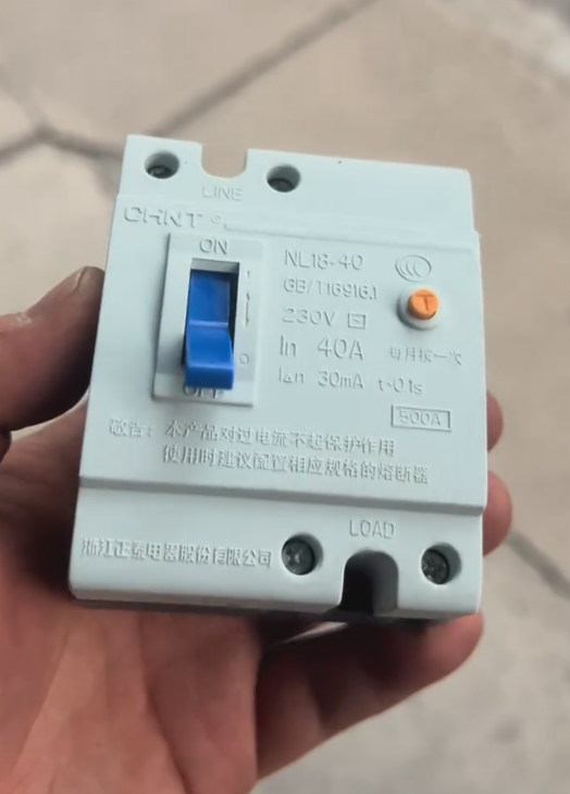

Chint NL18-40 Disjoncteur à courant résiduel
- Basic Product Information
Chint NL18-40 is an electronic fast-acting residual current protective circuit breaker, specially designed for single-phase circuits to provide leakage protection.
Paramètres de base:
Courant nominal: 40UN (frame size 40A)
Tension nominale: 230V (CA 50 Hz)
Numéro de pôle: 2P. (controlling live wire and neutral wire simultaneously)
Courant de fonctionnement résiduel nominal: 30mA (modèle standard, capable of cutting off power within 0.1 secondes)
Maximum Breaking Capacity: 500UN
Normes de conformité: FR 16916.1, CEI 61008-1
Fonctions principales:
Provides indirect protection against electric shock (quickly cuts off power when leakage current ≥ 30mA)
Prevents electrical fires caused by insulation damage of electrical equipment
Taille compacte, pouvoir de coupure élevé, reliable operation and good vibration resistance
Applications typiques:
Electric water heaters, solar water heaters
Vending machines, water dispensers
Household appliances such as refrigerators and washing machines
- Technical Characteristics
2.1 Principe de fonctionnement
Adopts zero-sequence current transformer for leakage detection: when the circuit is normal, the vector sum of currents in live wire and neutral wire is zero, and no induced voltage is generated in the transformer.
Quand une fuite se produit (par ex., human electric shock), the vector sum of currents is not zero, and the transformer generates an induced voltage.
After being amplified by the electronic component, the induced voltage triggers the release to cut off the power supply within 0.1 secondes.
2.2 Caractéristiques du produit
Electronic fast-acting type: response time ≤ 0.1 secondes
Inoperative to inrush current: insensitive to short-term inrush current, reducing maloperation
Uses main power supply as auxiliary power, no need for additional power source
- Guide d'installation
3.1 Préparation avant l'installation
Necessary Tools and Materials:
Tournevis cruciforme, pince à dénuder, crimping tool
Insulated gloves, ruban isolant
Matched copper conductors (select appropriate cross-sectional area according to load current)
M4 or M5 screws, plain washers, spring washers
Environment Inspection:
Installation altitude shall not exceed 2000m
Température ambiante: -5℃~+40℃, 24-hour average temperature shall not exceed +35℃
Relative humidity: ≤ 50% à 40℃, monthly average ≤ 90% in the wettest month (temperature ≥ 20℃)
The installation surface must be flat, dry and free of vibration, away from heat sources and magnetic fields (not exceeding 5 times the geomagnetic field strength)
3.2 Étapes d'installation
3.2.1 Fixing the Circuit Breaker
Align the mounting holes on the back of the circuit breaker with the mounting plate inside the distribution box.
Pass M4/M5 screws through the mounting holes, put on plain washers and spring washers in sequence, and tighten them to fix the breaker.
Ensure the circuit breaker is installed vertically (tilt angle ≤ 2°) to facilitate handle operation.
3.2.2 Câblage correct (Strictly Operate with Power Off!)
| Marquage des bornes | Contenu de la connexion | Remarques |
| L (ou 1) | Power live wire (phase wire) | Connect with top-in and bottom-out mode, no reverse connection allowed |
| N (ou 2) | Power neutral wire | Must be connected to ensure unobstructed neutral circuit |
| PE (si disponible) | Protective earthing wire | Reliably earthed to improve safety |
Key Wiring Points:
Strip the wire to a moderate length (about 10-12mm) to ensure the conductor is fully inserted into the terminal.
Use a crimping tool to ensure firm connection (looseness will cause overheating).
Tighten the wiring screws securely (but do not over-tighten to avoid damaging the terminals).
Check that all wirings are firm without looseness.
Confirm correct connection of live wire, neutral wire and earthing wire without wrong connection or missing connection.
Clean up debris inside the distribution box to ensure no conductive foreign matter.
3.3 Précautions de sécurité (Priorité absolue!)
3.3.1 Installation Safety
Must operate with power off, live installation or wiring is strictly prohibited.
Installation must be carried out by professional electricians (holding valid electrician certificates).
Avoid operating with wet hands during installation to prevent electric shock hazard.
3.3.2 Spécifications de câblage
Strictly distinguish between incoming terminal (power supply side) and outgoing terminal (load side), follow the principle of “top-in and bottom-out”.
Do not confuse neutral wire with earthing wire for connection, otherwise it will cause maloperation of leakage protection.
Ensure reliable connection of protective earthing wire (PE), disconnection is not allowed.
3.3.3 Prohibited Behaviors
It is strictly prohibited to test the performance of the circuit breaker by short-circuiting phase wire to ground or phase wire to phase wire (dangerous!).
Do not disassemble the circuit breaker shell without permission (there are high-voltage live components inside).
Do not adjust internal components at will after installation.
- Fonctionnement et entretien
4.1 Initial Operation
4.1.1 Test de fonctionnement
Après l'installation, confirm that all wirings are correct.
Close the main power switch.
Appuyez sur le “test button” on the circuit breaker, and the breaker should trip (disconnect) immediately.
Reset and close the breaker again, it should work normally.
If it does not trip during the test, it is strictly prohibited to put into use, and inspection or replacement should be carried out immediately.
4.1.2 Fonctionnement normal
Closing: Flip the handle upward to the “ON” position.
Opening: Flip the handle downward to the “OFF” position.
After tripping due to leakage: Eliminate the fault first, then flip the handle to the “OFF” position to reset, and then close the breaker again.
4.2 Entretien régulier
4.2.1 Inspection quotidienne
Inspect the appearance of the circuit breaker for damage, deformation or overheating marks once a month.
Check whether the wiring terminals are loose (especially in the initial use period and after heavy load operation).
Check whether the handle operation is flexible without jamming.
4.2.2 Test de fonctionnement
Conduct a leakage protection function test once a quarter (appuyer sur le bouton test, it should trip immediately).
If any abnormality is found, stop using it immediately and contact professional electricians for maintenance.
4.2.3 Nettoyage et entretien
Regularly clean dust on the surface of the circuit breaker (operate with power off).
Wipe with a dry cloth, avoid using liquid cleaners (which may cause insulation reduction).
Ensure good ventilation of the distribution box to prevent excessive internal temperature.
- Problèmes courants et solutions
| Problem Phenomenon | Causes possibles | Solutions |
| Failure to close | Short circuit or leakage on the load side | Troubleshoot the load circuit and close the breaker after repairing the fault |
| Tripping during normal operation | Line leakage or overload | Use an insulation megger to test insulation, reduce load or replace with a circuit breaker of larger capacity |
| No tripping when test button is pressed | Circuit breaker fault or wiring error | Check the wiring; if the wiring is confirmed correct, replace the circuit breaker |
Chint NL18-40 is a residual current protective circuit breaker specially designed for single-phase circuits, which can quickly cut off the power supply within 0.1 seconds when leakage occurs, effectively protecting personal safety and electrical equipment. Installation must be carried out in strict accordance with specifications by professional electricians to ensure correct and firm wiring. Regular maintenance and testing can ensure that it is always in good working condition, escorting your electricity safety.
Chint NL18-40 is an electronic fast-acting residual current protective circuit breaker. Its core working principle is based on current balance detection of zero-sequence current transformer, combined with electronic amplification components and electromagnetic release, to realize fast power-off protection in case of leakage faults. It can be specifically divided into two stages: normal working state and leakage fault state, and anti-interference design is realized in combination with product characteristics.
- Composition des composants de base
To understand the working principle, it is necessary to clarify its key internal components first:
- Zero-sequence Current Transformer: As the core detection component, it is a toroidal iron core, through which the live wire (L) et fil neutre (N) of the main circuit pass simultaneously.
- Electronic Amplification Component: Receives the induced signal from the transformer, performs signal amplification and discrimination, and is the core control unit of electronic leakage protection.
- Electromagnetic Release: Driven by the electronic component, it can quickly pull the main contacts of the circuit breaker to disconnect.
- Main Contacts and Operating Mechanism: Controls the on-off of the main circuit and links with the release.
- Test Circuit: Built-in test resistor and test button, used to simulate leakage faults and verify protection functions.
- Normal Working State
When there is no leakage or grounding fault in the circuit:
- The current in the live wire (L) and the current in the neutral wire (N) are equal in magnitude and opposite in direction, and the magnetic fields generated by the two currents cancel each other out in the iron core of the zero-sequence current transformer.
- No induced electromotive force is generated in the secondary winding of the transformer, and the electronic amplification component has no input signal and is in standby state.
- The electromagnetic release does not act, and the main contacts of the circuit breaker remain closed to supply power to the circuit normally.
- Leakage Fault State
Lorsqu'une fuite se produit dans le circuit (par ex., human electric shock, insulation damage and grounding of equipment):
- A part of the current will flow into the ground through the fault point, resulting in the live wire current being greater than the neutral wire current, and the vector sum of the two currents is no longer zero.
- Unbalanced magnetic flux will be generated in the iron core of the zero-sequence current transformer, and then a voltage signal proportional to the leakage current will be induced in the secondary winding.
- The electronic amplification component amplifies the weak voltage signal and outputs a trigger current to the electromagnetic release.
- After being energized, the electromagnetic release generates electromagnetic attraction, quickly pulls the operating mechanism of the circuit breaker, makes the main contacts disconnect within ≤ 0.1 secondes, cuts off the power supply, and avoids electric shock accidents or electrical fires.
- Principle Embodiment of Exclusive Product Characteristics
- Fast-acting Design: The electronic amplification component has extremely fast signal processing and trigger response speed. Combined with the instantaneous action characteristics of the electromagnetic release, it ensures power-off within 0.1 seconds after leakage, far exceeding the dangerous response time of human electric shock.
- Inoperative Characteristic to Inrush Current: The electronic component has a built-in signal discrimination circuit, which can distinguish between “instantaneous inrush current” (par ex., electrical starting current) et “sustained leakage current”, and only triggers tripping in response to sustained leakage current, effectively reducing maloperation.
- No Need for Additional Auxiliary Power Supply: The circuit breaker uses the main circuit power supply as the working power supply, without the need for external batteries or control power supplies, simplifying wiring, and the protection function can be restored by closing the breaker again after power-off.
- Working Logic of the Test Button
Le “test button” on the circuit breaker panel is a verification device for simulating leakage faults. Lorsqu'on appuie dessus:
- The built-in test resistor will directly shunt a small part of the live wire current to the neutral wire (or ground), artificially creating current imbalance between live wire and neutral wire.
- The zero-sequence current transformer detects the unbalanced current, triggers the subsequent electronic amplification and tripping actions, and the circuit breaker trips to verify whether the protection function is normal.
 from Schneider Electric’s EasyPact EZS+ Series (Dunhuang Series). Its official order code is EZSS630F3630, with the full model description EZS-S630 36kA TM630D 3P3D, designed for power distribution protection.")
, a core component for power distribution protection. It provides overload, short-circuit and earth fault protection for three‑phase circuits, and is a key protective device in industrial and commercial power distribution systems.")
 manufactured by LS Electric (formerly LS Industrial Systems / LG Industrial Systems).")


")


NH42-63-318x560.png "Commutateurs de transfert automatiques de type PC CHINT (ATS)NH42-63/4SZ")


