


Basic Overview
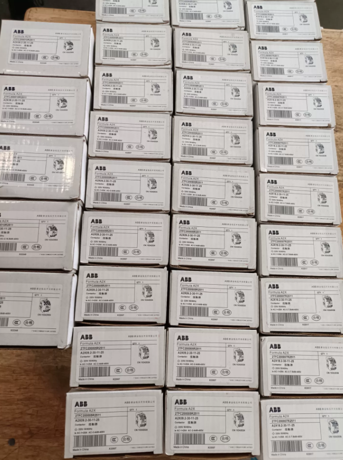
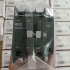
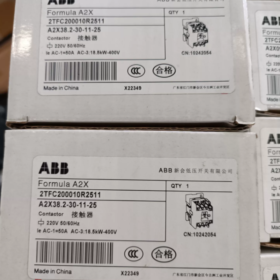
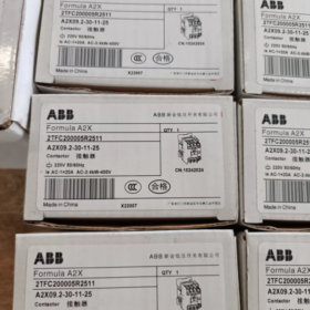
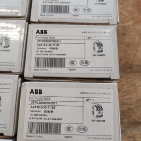
ABB A2X38/A2X38.2 is a 3-pole AC contactor belonging to the ABB Formula series. A2X38 is an earlier model (discontinued), while A2X38.2 is its upgraded replacement (currently in production). It is mainly used for controlling three-phase squirrel-cage motors and other power loads, and is suitable for industrial automation and building electrical systems. Ordering Code: 2TFC200010R2511
- Model Code Explanation
| モデルセグメント | 意味 |
| A2X | Formula series contactor with compact and cost-effective design |
| 38 | Rated operating current of 38A (AC-3, 400V) |
| 0.2 | Second-generation upgraded version (improved type) |
| 30 | 3-極主接点, normally open configuration |
| 11 | 補助接点構成: 1 通常は開いています + 1 通常は閉まっている |
| 13/25 | コイル電圧コード: 13 = 380-400VAC, 25 = 220-240VAC |
| 380V50/60HZ | Rated coil voltage and frequency |
Ⅲ. コア技術パラメータ
- 電気的パラメータ
| パラメータ項目 | 価値 | 備考 |
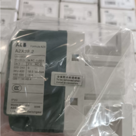
| 定格動作電流 (AC-3, 400V) | 38あ | Controlled motor power: 18.5kW (50Hz) / 20hp (60Hz) |
| 定格動作電流 (AC-1, 400V) | 50あ | 抵抗負荷 |
| 定格絶縁電圧 (Ui) | 690V | IEC規格 |
| Rated Working Voltage (うえ) | 400V (AC-3), 690V (AC-1) | |
| Control Coil Voltage | 220-240VAC, 380-400VAC, 110VAC, 24VAC/DC, 等. | 複数のオプションが利用可能 |
| Coil Frequency | 50/60Hz | Universal design, no adjustment required |
| Mechanical Service Life | 1,000万回以上の操作 | |
| Electrical Service Life (AC-3) | 100万回以上の操作 | Under rated load |
- 身体的特徴
| パラメータ項目 | 価値 |
| 取付方法 | DINレール取付 (35mm標準レール), slider design for one-hand disassembly |
| 全体の寸法 (mm) | Approximately 85×105×55 (Width × Height × Depth) |
| 重さ | Approximately 0.5kg |
| 保護クラス | IP20 (main body), IP00 for terminal blocks |
| Ambient Temperature | -25℃~+55℃ (operation), -40℃~+85℃ (storage) |
| 汚染度 | Degree 3 |
- Core Product Features
- コンパクトなデザイン: Small size, saving 30% of installation space, suitable for high-density distribution cabinets.
- High Efficiency and Reliability: Silver alloy contacts with arc resistance, low contact resistance and long service life.
- 簡単な取り付け: Quick snap-on fixing, auxiliary contact modules can be directly clipped without tools.
- Safety Assurance: Flame-retardant engineering plastic housing complying with UL94 V0 standard, built-in surge suppression (for some models).
- Modular Expansion: Accessories such as auxiliary contacts (up to 4 単位), mechanical interlocks, time-delay heads and surge suppressors can be added.
- 典型的なアプリケーションシナリオ
Direct start and stop control of three-phase asynchronous motors (≤18.5kW/400V)
Electrical control of equipment such as fans, ウォーターポンプとコンプレッサー
Switch control of non-motor loads such as heating and lighting systems
Building electrical systems and industrial automation production lines
Replacement of old contactors for equipment upgrading and transformation
- Complete Model and Ordering Information
| Complete Model | コイル電圧 | 補助接点 | Ordering Code | Status |
| A2X38-30-01 380V | 380VAC | 0 通常は開いています + 1 通常は閉まっている | 10221469 | Discontinued |
| A2X38.2-30-11-13 | 380-400VAC | 1 通常は開いています + 1 通常は閉まっている | 10242059 | Currently in Production |
| A2X38.2-30-11-25 | 220-240VAC | 1 通常は開いています + 1 通常は閉まっている | 10242060 | Currently in Production |
| A2X38.2-30-00-13 | 380-400VAC | No auxiliary contacts | 10242058 | Currently in Production |
Ⅶ. Installation and Wiring Specifications
Installation Steps:
- Confirm that the installation environment meets the range of -25℃~+55℃, free from severe vibration and corrosive gases.
- Select a 35mm standard DIN rail and ensure the mounting surface is flat.
- Align the contactor’s snap with the rail, press down and slide to fix (one-hand operation).
- Cut off all power supplies before wiring, and use a multimeter to confirm no voltage exists.
- Main circuit wiring: L1/L2/L3 → input terminals, T1/T2/T3 → output terminals.
- Control circuit wiring: A1/A2 → coil power supply, 13/14 → normally open auxiliary contacts, 21/22 → normally closed auxiliary contacts.
- After wiring is completed, gently pull the wires to confirm they are connected firmly without loosening.
Terminal Block Specifications:
主回路: M6 bolts, suitable for copper core wires with cross-sectional area of 1.5-16mm²
Control circuit: M3.5 bolts, suitable for copper core wires with cross-sectional area of 0.5-2.5mm²
VIII. Replacement Models and Compatibility
| Original Model | Direct Replacement Model | Upgraded Replacement Series | 備考 |
| A2X38 | A2X38.2 | AF38 Series | A2X38.2 is fully compatible with A2X38 in terms of installation dimensions and electrical performance |
| A2X38.2 | AF38-30-xx-xx | AF Series | AF series has advantages such as electronic coil (wide voltage range) and built-in surge suppression |
| AX38-30-xx | AX Series | Equivalent performance with slightly higher price |
- トラブルシューティングガイド
| 故障現象 | 考えられる原因 | ソリューション |
| コンタクタが引き込まれない | No voltage/low voltage on coil; コイル断線; 機械的な妨害 | Check the control circuit; Measure coil resistance (approximately several hundred ohms under normal condition); Clean foreign objects and lubricate moving parts |
| Excessive noise after pull-in | コイル電圧が低い; Oil stain/rust on iron core end face; Broken short-circuit ring | Adjust control voltage to rated value; きれいな鉄心端面; Replace coil assembly |
| 接点の過熱/アブレーション | Load overload; Poor contact of contacts; 配線の緩み | Check load current; Polish contacts or replace them; Re-tighten terminal blocks |
| Auxiliary contact failure | Contact wear; Wiring error | 補助接点モジュールを交換する; Check wiring polarity |
- Safety and Maintenance Precautions
- Power-off Operation: Cut off all power supplies before installation and maintenance, and hang the “No Switching On” sign.
- Regular Inspection: Conduct inspection every 6 月, including contact wear, terminal tightness and coil temperature.
- Contact Replacement: Replace the main contacts in time when the wear amount exceeds 1mm or the surface is severely ablated.
- 環境要件: Avoid use in humid and dusty environments; install a protective housing if necessary.
- Compatible Accessories: Only use auxiliary contacts, interlock devices and other accessories original or certified by ABB to ensure safety performance.


")


NH42-63-318x560.png "CHINT PC型自動切替スイッチ (ATS)NH42-63/4SZ")

")

