

- Product Positioning and Basic Parameters
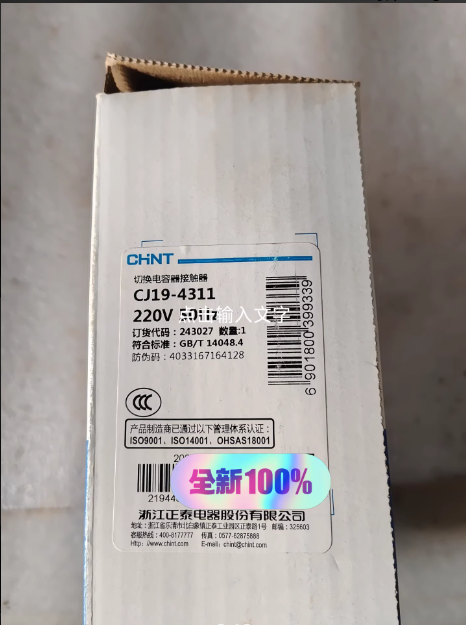
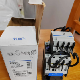
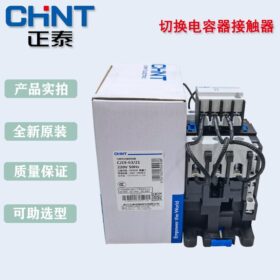
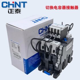
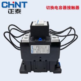
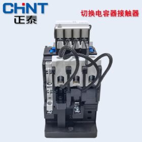
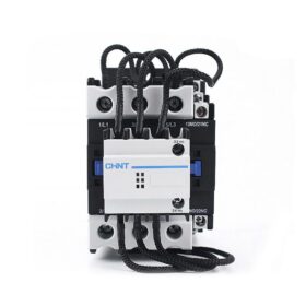
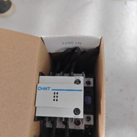
Product Positioning: The CJ19-4311 is a capacitor switching 接触器 belonging to Chint’s CJ19 series. Exclusively designed for low-voltage reactive power compensation systems, it is used to switch shunt capacitor banks and improve power factor.
モデルの解釈:
CJ19: Capacitor switching contactor series
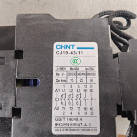
43: Basic specification code (rated current 43A)
11: 補助接点構成 (1 通常は開いています + 1 通常は閉まっている)
Core Parameters:
| パラメータ | 価値 |
| 定格電圧 | AC 380V/690V |
| 定格電流 | 43あ |
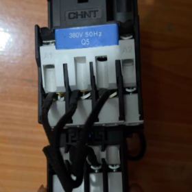
| コイル電圧 | 220V/380V (standard type) |
| Main Contact Pole Number | 3P |
| 補助接点 | 1NO+1NC |
| 機械的寿命 | 1,000,000 operations |
| 電気的寿命 | 100,000 operations |
| 保護クラス | IP10 |
| Compliance Standards | GB/T 14048.4, IEC/EN 60947-4-1 |
- Core Structure and Working Principle
- Structural Features
3-pole Main Contact System: Controls the on/off of capacitor banks
Inrush Current Suppression Device: Core component consisting of current-limiting resistors and a special contact system
補助接点: Provide status feedback for control circuits
Direct-acting Double-break Structure: Flexible operation and strong breaking capacity
Insulated Terminal Protection: Ensures operational safety
- Working Principle
コア機能: Reduces the closing inrush current (which can reach 10-20 定格電流の倍) when capacitors are switched on, protecting capacitors and the entire system.
Working Sequence:
Detailed Mechanism:
① Closing Process:
Energization of the coil generates a magnetic field that attracts the armature.
Phase 1: Current-limiting contacts (with permanent magnets) close first, and current pre-charges the capacitors through current-limiting resistors.
Phase 2: After several milliseconds (approximately 8ms), the main contacts close, short-circuiting the current-limiting resistors.
Phase 3: The permanent magnet in the current-limiting contacts is released by the spring action, opening the current-limiting branch.
Final Stage: Capacitors are directly powered by the main contacts, completing smooth switching-on.
② Opening Process:
The coil is de-energized, the spring resets, and the main contacts open first.
The auxiliary arc-extinguishing system suppresses switching overvoltage, protecting capacitors and the circuit.
Ⅲ. Detailed Explanation of Inrush Current Suppression Technology
Why Inrush Current Suppression is Necessary?
The initial voltage of capacitors is zero, resulting in a large voltage difference at the moment of closing and generating a huge charging current.
Inrush current can cause: contact ablation, shortened capacitor service life, and system voltage fluctuations.
Solutions of CJ19-4311:
Two-stage Closing: Pre-charging through current-limiting resistors (approximately 10-20Ω) to gradually increase the capacitor voltage.
Voltage Difference Reduction: When the main contacts close, the capacitor voltage is already close to the power supply voltage, reducing the closing inrush current to less than 5 定格電流の倍.
Extended Protection: Effectively protects contacts and extends the service life of contactors and capacitors.
- アプリケーションシナリオ
- Industrial Reactive Power Compensation Cabinets: Widely used in factory power distribution systems to improve power factor and reduce line losses.
- 商業ビル: Capacitor compensation in large electricity-consuming places such as shopping malls and office buildings.
- Power Systems: Reactive power compensation on the low-voltage side of substations to improve power grid quality.
- Motor Groups: Used in conjunction with motors for local reactive power compensation and improved equipment efficiency.
- Differences from Standard Contactors
| 特徴 | CJ19-4311 (Capacitor Switching Contactor) | Standard AC Contactor |
| コア機能 | Dedicated to capacitor switching and inrush current suppression | Controls general loads (モーター, lighting, 等) |
| Structural Features | Equipped with current-limiting resistors and a special contact system | No inrush current suppression device |
| Closing Sequence | Two-stage action: current limiting first, then main contact closure | Single-stage action: main contacts close directly |
| アプリケーションシナリオ | Only suitable for reactive power compensation systems | Widely used in various power control scenarios |
| 電気的寿命 | 100,000 operations (designed for high-frequency, high-inrush current capacitor switching scenarios) | Up to 1,000,000 operations (for non-inductive loads) |
- Selection Points
- Rated Current Selection: ≥ 1.5 × rated current of the capacitor bank (considering inrush current).
- Voltage Matching: Coil voltage must match the control circuit (220V or 380V).
- Contact Configuration: Select auxiliary contact types according to control requirements (11: 1NO+1NC).
- 環境条件: Altitude ≤ 2000m, ambient temperature -5℃ ~ +40℃.
The CJ19-4311 is an intelligent contactor specially designed for capacitor switching. Through two-stage closing + current-limiting protection technology, it solves the inrush current problem during capacitor switching and provides reliable protection for reactive power compensation systems. Compared with traditional contactors, it can effectively protect equipment and extend system service life, making it an ideal choice for improving power factor in industrial and commercial power systems.
> 注記: This product cannot be directly used for motor control. If motor control is required, the inrush current suppression device must be removed or a dedicated motor control contactor should be selected.
The core difference between the Chint CJ19-4311 capacitor switching contactor and standard AC contactors stems from the targeted design purpose—the former is optimized for capacitor switching scenarios, while the latter is intended for general load control. The specific differences can be compared structurally from the following dimensions, which are convenient for customer communication, selection instructions, or technical documentation:
- Core Difference Comparison Table (Including Quantitative Indicators)
| 比較次元 | Chint CJ19-4311 (Capacitor Switching Contactor) | Standard AC Contactor (例えば, CJX2 Series) |
| Core Design Purpose | Dedicated to switching shunt capacitor banks, suppressing closing inrush current, protecting capacitors and contacts | Controls general loads (モーター, lighting, heaters, 等) to realize start-stop control |
| Core Structural Differences | 1. Built-in current-limiting resistor + dual-contact system (current-limiting contacts + main contacts); | 1. No inrush current suppression device, only single-stage main contacts; |
| 2. Optimized contact materials (耐アーク性と耐溶接性); | 2. Standard contact materials; | |
| 3. Arc-extinguishing system adapted to overvoltage during capacitor switching | 3. Arc-extinguishing system adapted to general load breaking | |
| Working Sequence | Two-stage closing: | Single-stage closing: |
| Coil energization → Current-limiting contacts close first (5-10ms pre-charging) → Main contacts close (short-circuiting current-limiting resistors) → Current-limiting contacts open | Coil energization → Main contacts close directly with no pre-charging path | |
| Inrush Current Handling Capacity | Closing inrush current ≤ 5 定格電流の倍 (pre-charging via current-limiting resistors to gradually reduce voltage difference) | Closing inrush current ≥ 10-20 定格電流の倍 (during capacitor switching) with no suppression measures |
| Applicable Load Type | Only suitable for capacitive loads (shunt capacitor banks) | Suitable for inductive/resistive/mixed loads (モーター, ウォーターポンプ, heaters, 等) |
| Electrical Life Indicator | 100,000 operations (designed for high-frequency, high-inrush current capacitor switching scenarios) | Over 1,000,000 operations (for non-inductive loads) / 600,000 operations (for inductive loads), with longer service life in general scenarios |
| Overvoltage Protection | Built-in auxiliary arc-extinguishing system to suppress overvoltage during capacitor breaking (preventing capacitor breakdown) | No dedicated overvoltage protection; arc reignition is prone to occur when breaking capacitive loads |
| Contact Configuration | Fixed auxiliary contacts: 1NO+1NC (meeting feedback requirements of compensation cabinet control circuits) | Auxiliary contacts can be flexibly selected (例えば, 02, 11, 22, 等) to adapt to different control logics |
| Rated Parameter Matching | Rated current 43A, suitable for capacitor banks with rated current ≤ 28.7A (43A ÷ 1.5, considering inrush current margin) | Wide coverage of rated currents (例えば, 9あ, 12あ, 18A…95A), directly matching load rated current |
| Misapplication Risks | If used for motor control: current-limiting resistors are prone to burnout, and contact service life is significantly shortened | If used for capacitor switching: |
| 1. Contact ablation and welding (due to inrush current impact); | ||
| 2. Shortened capacitor service life (insulation aging caused by inrush current); | ||
| 3. Excessive system voltage fluctuations |
- In-depth Analysis of Key Differences (Key Points Frequently Asked by Customers)
- Why Can’t Standard Contactors Replace the CJ19-4311 for Capacitor Switching?
The initial voltage of capacitors is zero, resulting in an extremely large voltage difference at the moment of closing. When standard contactors close directly, an inrush current of 10-20 times the rated current will be generated:
Short-term risks: Contact arc ablation and welding (resulting in failure to break the circuit);
Long-term risks: Capacitor insulation breakdown and shortened service life (the normal service life of capacitors is 8-10 years, which may be reduced to 3-5 years if misused);
System risks: Voltage fluctuations in the power grid caused by inrush current, affecting the normal operation of other equipment.
Through the two-stage action of “current-limiting pre-charging + main contact short-circuiting”, the CJ19-4311 suppresses the inrush current to less than 5 定格電流の倍, fundamentally avoiding the above problems.
- Why Can’t the CJ19-4311 Replace Standard Contactors for Motor Control?
Motors are inductive loads. Although there is an inrush current during startup, the requirement is “fast and reliable closing”. しかし, the current-limiting resistor of the CJ19-4311 will lead to:
Insufficient motor starting voltage (voltage division by current-limiting resistors), reduced starting torque, and failure to start normally;
Current-limiting resistors are prone to overheating and burnout when passing motor operating current for a long time (current-limiting resistors are only designed for short-term pre-charging and are not suitable for long-term current carrying);
The two-stage closing sequence prolongs the starting time, affecting the response speed of motor control.
- Targeted Optimization of Contacts and Arc-extinguishing Systems
| Component | Optimization of CJ19-4311 | Design of Standard Contactors |
| Contact Material | Silver alloy (AgCdO or AgSnO₂) is adopted to enhance arc resistance and anti-welding capability | Standard silver contacts, meeting the breaking requirements of general loads |
| Arc-extinguishing Chamber | Narrow-slot arc extinguishing, adapted to high-frequency arcs during capacitor breaking | Wide-slot arc extinguishing, adapted to arc characteristics of inductive loads such as motors |
Ⅲ. Selection Decision Points (Quick Judgment Logic for Customers)
- If the load is a capacitor bank (reactive power compensation scenario): The CJ19 series capacitor switching contactor must be selected, and the rated current should be ≥ 1.5 × the rated current of the capacitor;
- If the load is general equipment such as motors, heaters, and lighting: A standard contactor (例えば, CJX2, CJ20 series) should be selected, with a rated current ≥ 1.1 × the rated current of the load (for inductive loads) / × 1.0 (for resistive loads);
- Core judgment basis: Whether the load type is capacitive—dedicated contactors are selected for capacitive loads, and standard contactors are selected for other loads. Cross-substitution is not allowed.
The essential difference between the two is “scenario specificity”: the CJ19-4311 is a “customized model for capacitor switching”, which solves the inrush current pain point through structural and sequence optimization; the standard contactor is a “general-purpose model”, pursuing broad applicability and long service life in general scenarios. When explaining to customers, emphasis can be placed on the “risk cost of misuse” (such as contact replacement, capacitor damage, and system failure) to help customers understand the value of dedicated products.


")


NH42-63-318x560.png "CHINT PC型自動切替スイッチ (ATS)NH42-63/4SZ")

")

