 コンタクタ,サーキットブレーカー,センサー,エンコーダ,PLC,コンバータ

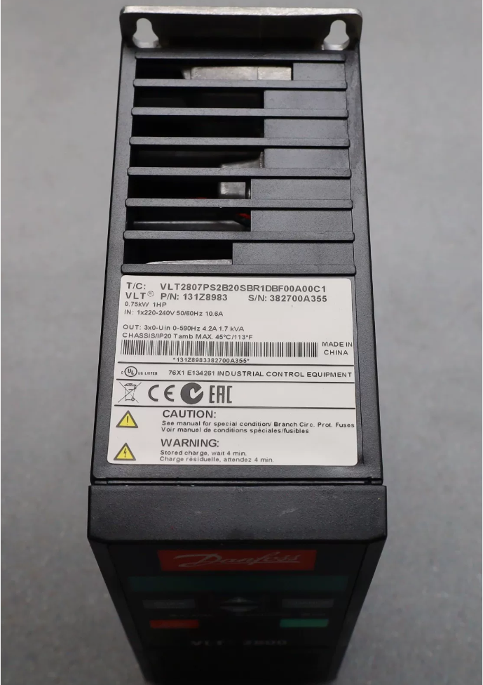

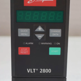
Typical Application Scenarios for ダンフォス VLT2807 (0.75 kW)
The VLT2807 is a small-size general-purpose open-loop V/F frequency converter. It supports Constant Torque (CT) / 可変トルク (VT) selection, built-in PID and AMA auto-adaptation. Compact side-by-side installation is supported. Mainly used for OEM equipment, HVAC-light-industry and assembly-line drives. Not suitable for high-precision vector control, heavy-shock loads or high-inertia lifting applications.
状態: 製造中止. Legacy compact general-purpose 周波数変換器, 0.75 kW, widely used for fans, パンプス, assembly lines and small-size drive equipment.
- モデルのデコード (Full-model example: VLT2807PT4B20SBR1DBF12A00C1)
28: VLT2800 series
07: Power rating 0.75 kW / 1HP
P: Process variant
T: 三相入力
4: 380-480 VAC
B: Book-style construction, IP20
R1: Built-in Class A1 EMC filter; R0 = No EMC filter
D: No brake chopper; B = Built-in brake chopper
F12: LCP local control panel; F00 = Without panel
Example order number: 134H2368 (with EMC filter and control panel)
- コアの電気仕様 (380-480 V version)
| アイテム | 仕様 |
| 定格電力 | 0.75 kW (1HP) |
| 電源 | 3×380‑480 V ±10 %, 50/60 Hz |
| 定格出力電流 | 4.2 あ |
| 皮相電力 | 1.7 kVA |
| 保護クラス | IP20 |
| スイッチング周波数 | 4‑16 kHz adjustable |
| 放熱 | Cabinet mounting; maintain 100 mm clearance top and bottom |
| 正味重量 | 約. 2.1 kg |
A single-phase 220 V version VLT2807 (1×220-240 V) is also available, same 0.75 kW power rating, 4.2 A output current.
- Hardware Interface Overview
Main-circuit Terminals
入力: L1, L2, L3; モーター出力: U, V, W; PE protective earth; Brake resistor terminals (selected variants only)
Control Terminals (VLT2800 series)
デジタル入力: 18, 19, 27, 29, 33
Analogue inputs: 53 (電圧/電流), 60 (現在)
Analogue output: 42
RS485: 68/69 (Profibus-DP via optional expansion card)
サポートされている機能: Multi-speed, スタート/ストップ, PID, analogue reference, pulse reference, precision stop, auto-restart, AC braking.
- 主な特長
- Quick Menu: Fast commissioning with 12 key motor-setup parameters; supports AMA motor auto-adaptation (Parameter P107).
- V/F制御; selectable constant-torque / variable-torque mode; built-in PID for constant-pressure water-supply and fan applications.
- Supports brake resistor and AC braking; fault auto-reset and auto-restart.
- Optional Profibus-DP and DeviceNet fieldbus expansion cards.
- LCP panel supports parameter copy for batch-unit commissioning.
- Discontinued-product Replacement Solution
公式の直接交換品: VLT Midi Drive FC280, 0.75 kW, 380-480 V
Highly compatible mounting dimensions and terminal layout; plug-in terminals are reusable; parameters can be migrated.
Added Safe Torque-Off (STO) safety function with enhanced overall performance.
Alternative reference: FC-051 (エコノミータイプ, not direct terminal-compatible; requires full rewiring for retrofit).
- 一般的な故障コード
Err 8: DC-bus under-voltage. 入力電圧を確認してください, supply voltage drop or momentary power loss.
Err 1: 過電流; Err 4: 地絡; Err 14: 地絡; Err 16: 短絡; Err 29: 過熱.
- Second-hand Unit Inspection Checklist
- 目視チェック: Swollen electrolytic capacitors, PCB corrosion, fan ageing.
- Power-on without motor: Check for alarms; test all panel keys.
- Run with small-size motor at no-load; verify three-phase output-voltage balance.
- Verify power rating, presence of EMC filter and built-in brake chopper.
- Back-up complete parameter set. Electrolytic capacitors are the main failure risk on this legacy series.
- Variable-torque loads (ファン & パンプス, VT mode)
Torque decreases with speed; energy-saving operation; built-in PID for pressure/flow closed-loop regulation.
- Small centrifugal fans: Workshop exhaust fans, cabinet cooling fans, air-handling-unit fans, small waste-gas-treatment fans.
- Water-supply / 循環ポンプ: Small-scale constant-pressure water supply, cooling-water circulation pumps, metering pumps, process make-up pumps.
- HVAC terminal-units and small-building ventilation systems.
✅ 利点: PID sleep-wake-up function; soft-start to minimise water hammer; prominent energy-saving effect.
- Constant-torque loads (CT mode, 160 % overload for 1 min)
Torque remains largely independent of speed; sufficient starting-torque required. Mainly for assembly-line and light-industrial machinery.
- Conveying equipment: Small belt conveyors, ローラーコンベア, チェーンコンベヤ, sorting-line equipment.
- 包装機械: Small packaging machines, sealers, ラベラー; precision-stop function for station positioning.
- Mixing-stirring equipment: Small mixing tanks, blenders and agitators.
- Light-industry & 繊維: Auxiliary drives for small-size unwinding/winding, textile-machinery and cutting equipment.
- 押し出し & small-process equipment: Micro-extruders, material feeders.
注記: For long-time operation below 10 Hz, standard-motor cooling deteriorates. Variable-frequency motor with separate cooling fan is recommended.
Ⅲ. Industry Sectors
- 空調設備: Fans and circulation pumps (most-common application).
- 包装 & light-industry OEM: Small-power drive units integrated into machinery.
- 水処理: Small-size water-supply and chemical-dosing metering pumps.
- 食べ物 & 飲み物: Small conveyors and agitators.
- General-factory automation: Auxiliary drives for production-lines.
- Unsuitable Operating Conditions
- High-inertia hoisting / lifting machines (only permitted for light-duty auxiliary mechanisms, not for main lifting drives).
- Applications requiring closed-loop vector control or high-dynamic-response servo-level performance.
- Continuous heavy-duty operation with frequent shock-loading.
- Long-term high-speed spindle operation above 400 Hz.
- Configuration Tips for Typical Applications
- ファン / ポンプ: Select R1 variant with built-in EMC filter; set P101 to Variable-Torque (VT).
- コンベア / agitator: Requires high starting-torque; set P101 to Constant-Torque (CT). For frequent braking duty, select variant with built-in brake chopper (suffix-B in model code).
- Fieldbus control: Add Profibus-DP option card for PLC interfacing.
Complete Technical Specifications of Danfoss VLT2807 (VLT2800 series)
状態: 製造中止. 0.75 kW, available in single-phase 220 V and three-phase 380-480 V versions.
- Power-stage Electrical Parameters
① Three-phase 3×380-480 V (widely-used VLT2807PT4)
| アイテム | 仕様 |
| モーター定格出力 | 0.75 kW / 1HP |
| Continuous rated output current Iinv | 2.1 あ |
| 60‑second overload current | 3.3 あ (160 % overload for 1 min) |
| 皮相電力 | 1.7 kVA |
| Input supply | 3×380‑480 VAC ±10 %, 50/60 Hz |
| Rated input current | 1.9 あ |
| 60‑s maximum input current | 3.0 あ |
| DC‑bus voltage range | 540‑800 VDC |
② Single-phase 1×220-240 V (VLT2807P1)
| アイテム | 仕様 |
| モーター定格出力 | 0.75 kW / 1HP |
| Continuous rated output current Iinv | 4.2 あ |
| 60‑second overload current | 6.7 あ (160 % overload for 1 min) |
| 皮相電力 | 1.7 kVA |
| Input supply | 1×220‑240 VAC ±10 %, 50/60 Hz |
| Rated input current | 10.6 あ |
| 60‑s maximum input current | 16.7 あ |
| DC‑bus voltage range | 280‑380 VDC |
Overload rating: Constant-Torque (CT): 160 %, 60 s; Variable-Torque (VT): 110 % continuous.
- パフォーマンスパラメータ
Control principle: Open-loop V/F control. User-programmable V/F curve; no closed-loop vector capability.
Output-frequency range: 0-1000 Hz; factory default 0-50 Hz.
Carrier switching frequency: 4-16 kHz adjustable, factory default 4 kHz. Current-derating applies at higher switching frequencies.
Motor auto-adaptation AMA: Static AMA supported (P107).
Acceleration / deceleration times: 0.05-3600 s; four independent ramp-time sets selectable.
PIDコントローラー内蔵: Closed-loop for fans/pumps; sleep-wake-up, ドライラン保護, no-flow detection.
Braking modes: AC-braking; optional built-in brake chopper (-B model suffix) for external brake-resistor; DC-bus paralleling for load-sharing.
Restart functions: Fault auto-reset & restart, flying-start, power-drop protection.
Ⅲ. Control-terminal Ratings
デジタル入力 (から: Terminals 18, 19, 27, 29, 33)
量: 5 デジタル入力; internal 24 V supply; compatible with NPN / PNP logic.
機能: スタートストップ, 前進/後進, マルチスピード, fault-reset, pulse reference, output-inhibit.
Analogue Inputs
- Terminal 53: 0-10 V voltage / 0-20 ミリアンペア / 4-20 ミリアンペア, 設定可能.
- Terminal 60: 4-20 mA current-input only.
Analogue Output (Terminal 42)
1 analogue output: 0-20 ミリアンペア / 4-20 mA programmable. May output frequency, output-current, output-voltage and other process variables.
リレー出力
1 リレー出力; contact rating AC250 V / 3 あ. Configurable for fault-signal, drive-running, frequency-reached and other status-signals.
通信インターフェース
- 標準: RS485 (Terminals 68/69), supports Modbus-RTU and Metasys-N2 protocols.
- Optional expansion cards: プロフィバス-DP, デバイスネット (hardware option required).
- 機械式 & 環境仕様
| アイテム | 仕様 |
| エンクロージャの種類 | Book‑style, IP20; cabinet‑mount only |
| 寸法 (高さ×幅×奥行き) | 200 × 75 × 168 mm |
| 正味重量 | 約. 2.1 kg (without panel); 2.2‑2.6 kg with panel+filter |
| 取り付け | Vertical wall‑mount; side‑by‑side tight‑mount allowed; ≥100 mm vertical clearance top/bottom |
| Main‑circuit terminal torque | 0.5‑0.6 Nm; PE‑earth terminal 2‑3 Nm |
| 使用周囲温度 | 0‑50 °C; derating above 45 °C |
| 保管温度 | ‑20 °C ~ +65 °C |
| 高度 | No derating ≤1000 m above sea‑level; derating required >1000 メートル |
| 保護クラス | IP20; not for outdoor installation |
- Maximum Permissible Motor-cable Length
Unshielded cable: 200 メートル (with motor-reactor fitted).
Shielded cable: 100 メートル (with motor-reactor fitted).
R1 version (built-in A1-EMC filter): マックス. 50 m shielded cable.
R0 version (内蔵フィルターなし): マックス. 25 m shielded cable.
- EMC & Safety Standards
R1 variant: Complies with EN55011 Class A1 (industrial EMC filter). R0: No internal filter.
承認: UL, CE. No built-in Safe-Torque-Off (STO) (STO introduced on successor FC280).
Ⅶ. Model-code Breakdown (VLT2807 full-model string)
VLT2807 P T 4 B 20 S B R1 D B F12 A00 C1
P = Process; T = Three-phase; 4 = 380-480 V; B = Book-style; 20 = IP20
R1 = Built-in A1-EMC filter; R0 = No filter
D = No brake chopper; B = Built-in brake chopper
F12 = With LCP keypad; F00 = Without keypad
VIII. Reference Order Numbers
VLT2807PT4B20SBR1DBF12A00C1 (フィルター付き + panel): 134H2368
VLT2807PT4B20STR0DBF00A00C1 (フィルターなし, no panel): 195N1013
- Replacement-model Parameter Comparison
FC280 Midi Drive 0.75 kW, 380-480 V
Identical power rating; high terminal-hardware compatibility; STO safety-function integrated; standard RS485 Modbus. Direct hardware replacement for VLT2807.
Control Modes of Danfoss VLT2807
Parameter P100 (Configuration Mode) defines the high-level drive-operating mode. The underlying motor algorithm is fixed as open-loop V/F. Vector-control and field-oriented control are not supported.
- Underlying Motor-control Algorithm
- オープンループV/F (Voltage-to-Frequency) コントロール (only motor-control algorithm)
Selectable Constant-Torque (CT) / Variable-Torque (VT) via P101; custom V/F curve available.
Static AMA motor auto-adaptation is supported for motor-stator-voltage-drop compensation.
No encoder-based closed-loop speed-vector control; not for high-precision speed-regulation.
- Four Operating-mode Settings of Parameter P100
| P100 Value | Mode Name | 説明 | 代表的な用途 |
| 0 | Open‑loop speed control | V/F open‑loop; speed reference from external source; no feedback | ファン, パンプス, コンベア, general‑purpose speed‑regulation (most‑used setting) |
| 1 | Closed‑loop speed control | Hardware‑encoder interface is not available on VLT2807. This is a residual menu‑option and cannot be used in practical projects. | Encoder‑based closed‑loop speed‑control (not implementable on VLT2807) |
| 2 | 予約済み | Spare setting | Not used |
| 3 | Process‑PID closed‑loop control | Built‑in PID controller, regulates against pressure/flow process‑feedback signal | Constant‑pressure water‑supply, constant‑air‑volume fans; pump‑sleep function available |
✅ Practical field-usage: P100=0 Open-loop speed control and P100=3 Process-PID closed-loop control.
Ⅲ. Reference-source & Command-source Options
- Local panel control (LCP keypad)
Parameter 002=1 LOCAL
スタートストップ, forward/reverse and frequency reference set via keypad buttons.
Used for commissioning and local manual operation of standalone units.
- External-terminal remote control (Parameter 002=0 REMOTE)
① Analogue-reference speed setting
Terminal 53: 0-10 V / 0-20 ミリアンペア / 4-20 ミリアンペア; potentiometer-speed-setting.
Terminal 60: 4-20 mA current-input only.
Terminal 33 configurable as pulse-frequency reference, max. 67.6 kHz.
② Digital-terminal control
Multi-speed: Combinations of digital-input terminals, まで 8 preset fixed-speed setpoints.
Start-stop and direction: Terminal 18 for start, Terminal 19 for reverse.
Jog-function, precision-stop, fault-reset, output-inhibit.
- Fieldbus communication control
- Native RS485 (Terminals 68/69): Modbus-RTU, Metasys-N2. PLC controls start-stop, speed-reference and parameter-access.
- Optional expansion cards: プロフィバス-DP / DeviceNet for bus-based command & reference.
- Mixed-source control
Command-source and reference-source may differ. 例: Terminals for start-stop while bus provides frequency-reference; or bus for start-stop with potentiometer-analogue reference.
- Braking Modes
- AC-braking: Low-frequency AC excitation for fast deceleration; 追加のハードウェアは必要ありません.
- DC-injection braking: DC injection to lock motor-shaft during stop; configurable braking-time and braking-voltage level.
- Brake-chopper + brake-resistor (-B model suffix): Energy-dissipation braking for high-inertia regenerative-load applications.
- Start-stop Logic Types
- Ramp-start-stop: Smooth speed-ramp-up / ramp-down following acceleration-deceleration times.
- Flying-start: Detect and synchronise to already-rotating motor speed.
- Precision-stop: Counter-based stop for conveyor-station positioning.
- Free-coast stop; Fast-stop OFF3.
- Unsupported Control Functions
❌ No vector control (no VVC-plus, no flux-vector).
❌ No encoder-based closed-loop speed-control (no hardware encoder-interface).
❌ No positioning or servo-position-control.
❌ No Safe-Torque-Off (STO).
Typical Application-configuration Examples
- General fan / conveyor speed-regulation: P100=0 Open-loop speed; terminal-start-stop + potentiometer reference on Terminal 53.
- Constant-pressure water-supply pump: P100=3 Process-PID closed-loop; 4-20 mA pressure-transmitter connected to Terminal 60.
- PLC fieldbus control: P100=0 Open-loop speed; RS485 Modbus-RTU; start-stop and speed-reference fully via bus.





NH42-63-318x560.png "CHINT PC型自動切替スイッチ (ATS)NH42-63/4SZ")



