 コンタクタ,サーキットブレーカー,センサー,エンコーダ,PLC,コンバータ

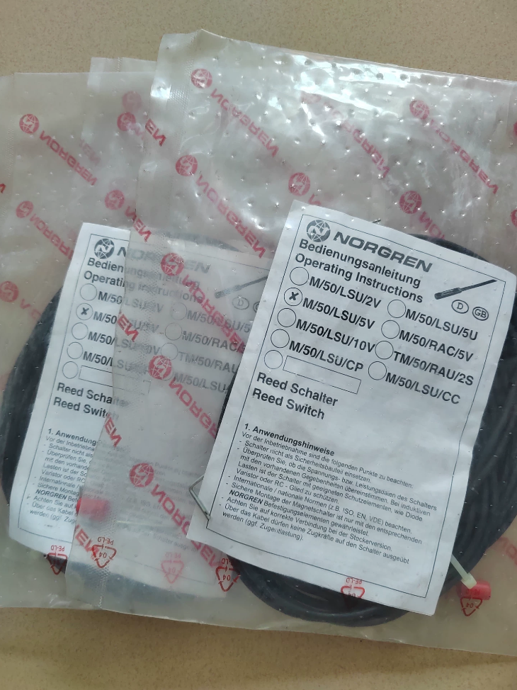

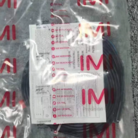
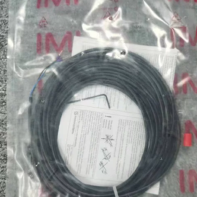
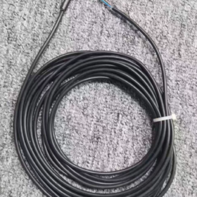
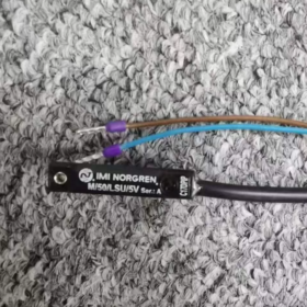
モデルの内訳
M/50: 製品シリーズ, cylinder magnetic proximity switch
LSU: Reed type, 通常開 (いいえ), LEDインジケーター付き, cable outlet
5: ケーブル長 5 メートル
V: Universal wide voltage version (10~170V AC/DC)
コアアプリケーション
Detect full stroke position of pneumatic cylinder pistons (extended/retracted position signals for feedback to PLCs or relays)
- コアの電気仕様
| パラメータ | 仕様 |
| 動作原理 | Reed contact (mechanical magnetic actuation) |
| 接点構成 | 通常開 (いいえ): open without magnet, closed near magnetic ring |
| 動作電圧 | 10~170 V AC/DC; compatible with general 240V AC/DC systems |
| Max Switching Current | 0.18 あ |
| Max Switching Power | 10 W |
| 応答時間 | 1.8 MS |
| インジケーターライト | Built-in yellow LED, illuminated upon magnetic actuation |
| 侵入保護 | IP66 (防塵, protected against high-pressure spray) |
| 動作温度 | -20 ℃~ +80 ℃ |
| ケーブル仕様 | 5m PVC cable, 2-core 0.25mm² |
| 準拠基準 | で 60947-5-2, RoHS, 到着 |
| 起源 | ポーランド |
- 機械式 & インストール
3.1 適合シリンダ
Norgren RA/8000 and KA/8000 series profile cylinders; matching ring/clamp mounting brackets (QM/33 series), compatible with bore sizes 10/20/25/32/40/50/63/80/100mm.
3.2 取付方法
Profile T-slot cylinders: Slide switch directly into cylinder T-slot, no extra brackets required
Round tie-rod cylinders: Fixed via optional metal clamp brackets
3.3 ハウジング材質
エンジニアリングプラスチック, resistant to oil contamination and industrial vibration
- Cross-Series Selection Guide (Quick Differentiation)
- M/50/LSU/2V: 2-meter cable, all other parameters identical to 5V variant
- M/50/LSU/5U: 5-meter cable, low-voltage DC model (10~30VDC)
- M/50/EHP Series: Electronic solid-state non-contact (PNP/NPN), high-frequency long-life replacement for reed switches
- アプリケーションシナリオ
自動組立ライン, 包装機械, machine tool pneumatic fixtures
Stroke limit detection for material handling cylinders, position sensing for stamping equipment cylinders
Position feedback for general pneumatic actuators, compatible with AC/DC control cabinets
- Operating Precautions
- Reed contacts cannot drive heavy loads; an interposing relay must be used for signal transfer. Direct driving of solenoid coils is prohibited.
- Avoid environments with strong magnetic fields or heavy electromagnetic interference from welding equipment to prevent false triggering.
- Minimum cable bending radius ≥ 10× cable outer diameter; corrugated tubing protection recommended for continuously vibrating equipment.
- Replace with electronic solid-state M/50 switches if ambient temperature exceeds 80℃.
- Part Numbers for Matching Accessories
Clamp bracket for Ø20 bore: QM/33/020/22
Clamp bracket for Ø32 bore: QM/33/432/22
Quick switch retaining clip: QM/27/2/1
IMI Norgren M/50/LSU/5V Reed Magnetic Switch Official Full Installation Manual
Document Basic Information
モデル: M/50/LSU/5V (M50LSU5V)
製品タイプ: Normally Open reed magnetic position switch, built-in yellow LED, 5m 2-core cable, wide voltage 10~170V AC/DC
適合シリンダ: Norgren RA/8000 & KA/8000 series T-slot profile cylinders, round tie-rod cylinders
侵入保護: IP66
規格: で 60947-5-2, RoHS, 到着
Table of Contents
- Unpacking Inspection & モデルの検証
- 機械的設置 (Two Solutions: T-Slot Profile / Round Tie-Rod Cylinders)
- Selection List for Matching Mounting Brackets
- Electrical Wiring Specifications & Wiring Diagrams
- Commissioning Procedures
- 環境 & 設置禁止事項 (重大な制限事項)
- トラブルシューティング マトリックス
- 定期的なメンテナンス
- Quick Reference Technical Specifications
1 Unpacking Inspection & モデルの検証
1.1 Incoming Goods Inspection
- Verify laser-engraved model on switch body: M/50/LSU/5V; confirm 5-meter cable length
- Inspect housing for cracks, cable root for damage, intact LED viewing window
- 付属品: Retaining fixing screw pre-installed on unit; clamp brackets must be ordered separately for round cylinders
1.2 モデルセグメントの定義
M/50: Magnetic proximity switch series
L: Equipped with LED indicator
SU: General-purpose reed Normally Open, ケーブルコンセントタイプ
5: 5-meter cable length
V: Universal wide voltage model, 10~170V AC/DC
2 Mechanical Installation Operating Guide
2.1 T-Slot Profile Cylinders (Norgren RA/KA Series, Recommended Mounting)
- Loosen flat-head fixing screw at switch tail and open clip slot
- Fully insert switch clip into cylinder side T-slot, slide to target detection position (magnet position at cylinder full extension/retraction)
- Fine-tune horizontal position: Optimal trigger point when yellow LED stays steadily illuminated as piston magnet passes switch
- Tighten tail fixing screw with flat screwdriver, torque 0.8~1.0 N·m to prevent shifting from vibration
- Route cable outlet downward or sideways; upward routing is forbidden to avoid water accumulation
2.2 Round Tie-Rod Cylinders (No T-Slot, Clamp Bracket Mounting)
- Select matching QM/33 series metal clamp per cylinder bore size
- Fit clamp onto cylinder barrel, pre-tighten clamp screws and slide to detection position
- Clip M/50 switch into integrated clamp retainer, fasten switch fixing screw
- Fully tighten clamp to prevent sliding during operation; clamp torque 1.2~1.5 N·m
2.3 Mountig Position Standards
Sensing face flush against cylinder outer wall, zero clearance, no metal interlayer
Minimum 20mm spacing between two switches on one cylinder to avoid mutual magnetic interference
Keep clear of strong magnetic inserts on cylinder end caps (buffer magnets)
3 Matching Mounting Bracket Part Number List
| Accessory Part No. | 応用 | Compatible Bore Size |
| QM/27/2/1 | Universal clip for profile cylinders (identical clip pre-fitted to switch) | All T-slot cylinders |
| QM/33/010/22 | Aluminum clamp for round cylinders | Ø10 |
| QM/33/020/22 | Aluminum clamp for round cylinders | Ø20/25 |
| QM/33/432/22 | Aluminum clamp for round cylinders | Ø32/40 |
| QM/33/463/22 | Aluminum clamp for round cylinders | Ø50/63/80/100 |
4 Electrical Wiring Specifications (Core Chapter)
4.1 Cable Definition (2-core PVC cable, 0.25mm²)
Brown wire (BN): Positive power / AC live line
Blue wire (これ): Negative power / AC neutral line
Internal reed Normally Open contacts close circuit when magnetic ring approaches, yellow LED illuminates
4.2 Two Standard Wiring Schemes
スキームA: Drive PLC Digital Input (最も一般的な)
- DC24V System: BN connected to +24V, BN wired to PLC input terminal, PLC common terminal connected to 0V
- AC220V System: BN connected to Live (L), BU connected to Neutral (N) of PLC AC input module
> WARNING: Max switching current of reed contacts is 0.18A; direct driving of solenoid coils is strictly prohibited!
スキームB: Interposing Relay for Heavy Load Transfer
- Relay coil wired in series with BN & BU circuit
- Relay contacts control high-current loads including solenoid valves and indicator lights
4.3 Critical Wiring Restrictions
- No energization under no-load conditions (unloaded circuit instantly burns reed contacts via electric arcing)
- Separate signal wiring from power cables (インバータ, motor leads), minimum 10cm spacing to avoid interference-induced false triggering
- Minimum cable bending radius ≥10× cable outer diameter; repeated bending/pulling at cable root forbidden
- Isolate full cabinet power supply before wiring work to avoid electric shock and contact burnout
4.4 Cable Routing Protection
Vibrating equipment: Route cables through corrugated tubing; reserve 5~8cm slack at switch cable root
Oil mist & spray environments: Wrap cable joints with waterproof tape; seal cable entry points inside control cabinets
5 Standard Full-Unit Commissioning Procedures
ステップ 1 Mechanical Position Calibration
Manually actuate cylinder piston to slide built-in magnet slowly across switch sensing zone
Magnet at detection position: Yellow LED remains continuously lit
Magnet away from detection position: LED fully off
If LED flickers, fine-adjust switch horizontal position for stable triggering without strobing
ステップ 2 Electrical Signal Testing
- 電源を入れる, measure circuit continuity via series-connected multimeter
- Magnet in detection zone: Circuit closed (resistance near 0Ω)
- Magnet away from detection zone: Circuit open (無限の抵抗)
ステップ 3 Automated Cycle Verification
Run cylinder reciprocating cycle 10 times under no-load; confirm stable signal output at every stroke end without signal loss or false triggering
6 環境 & 設置禁止事項 (Forbidden Operations)
- Temperature Limit: Operating range -20℃ ~ +80℃; replace with M/50 electronic switches above 80℃
- Magnetic Interference: Keep away from welding equipment, strong permanent magnets, サーボモーター, inverter output cables to prevent false operation
- Impact Protection: Prohibit striking or dropping switch unit; internal glass reed tube fractures easily upon impact
- Chemical Environments: Install protective covers in strong acid, alkali or high-concentration solvent environments; plastic housing will corrode and crack
- Pressure Washing: IP66 rating only resists low-pressure spray; direct high-pressure water jet at cable root causes water ingress and unit failure
- Overloaded Operation: Switching power must not exceed 10W; interposing relay mandatory for higher power loads
7 トラブルシューティング マトリックス
| 故障の症状 | 根本的な原因 | Stepwise Remedial Actions |
| LEDオフ, no signal when magnet reaches detection point | 1. Broken/reversed wiring | 1. Cut power, re-crimp terminals and verify brown/blue wiring |
| 2. Loose/shifted switch mounting | 2. Tighten fixing screw and recalibrate position | |
| 3. Internal reed damage | 3. Replace with new M/50/LSU/5V unit | |
| Flickering LED, intermittent signal loss | 1. Excessive gap between switch and magnet | 1. Mount switch flush against cylinder wall to eliminate clearance |
| 2. Severe electromagnetic interference | 2. Route signal cables separately and add shielding | |
| 3. Internal wire breakage at cable root | 3. Trim damaged cable segment and re-terminate | |
| Switch burns out immediately after power-up | 1. Direct driving of heavy solenoid loads | 1. Install interposing relay for load transfer |
| 2. Input voltage exceeding 170V | 2. Match system voltage and add voltage regulator | |
| 3. Short-circuit energization under no load | 3. Series load must be fitted before energizing circuit | |
| Switch slides out of position during cylinder operation | Insufficient screw tightening torque, loosening from vibration | Retighten fixing screw to 0.8~1 N路m; add anti-loosening washers for high-vibration machinery |
8 Routine Maintenance Specifications
- 日常点検: Check LED trigger status, inspect cables for abrasion or cracking
- Weekly Maintenance: Clean oil and dust from switch surface; prevent metal debris adhesion to housing
- Monthly Inspection: Retorque fixing screws to avoid loosening from long-term vibration
- Semi-Annual Calibration: Verify signal stability; maintain spare replacement units for mass production line
9 Core Product Technical Specifications (Installation Reference)
| パラメータ | M/50/LSU/5V Specification |
| Sensing Element | Reed tube, 通常開 (いいえ) |
| 動作電圧 | 10~170V AC/DC |
| Max Switching Current | 0.18あ |
| Max Switching Power | 10W |
| 応答時間 | 1.8MS |
| インジケーターライト | 黄色のLED, illuminated when closed |
| ケーブル仕様 | 5メートル, 2×0.25mm² PVC |
| 侵入保護 | IP66 |
| 動作温度 | -20℃~+80℃ |
| ハウジング材質 | 難燃性エンジニアリングプラスチック |
| Compliance Standard | で 60947-5-2 |
一般的な障害, 原因 & Remedial Solutions for Norgren M/50/LSU/5V (M50LSU5V) Magnetic Switch
This reed-contact magnetic switch has four primary fault categories: no output signal, flickering signal, burnt switch body, mechanical shifting. Inherent reed switch weaknesses (susceptible to high current, heavy impact and high temperature) are the leading failure triggers.
1 故障 1: LED unlit, no output signal when cylinder magnet arrives (Most Common Failure)
Potential Causes
- Mechanical mounting offset
Loosened fixing screw shifts switch outside magnet sensing zone; excessive gap between switch and cylinder barrel.
- Wiring faults
Broken conductors from repeated bending at cable root, loose terminal crimps, cable insulation cut by sharp metal edges leading to short/open circuits (AC/DC polarity insensitive).
- Abnormal cylinder magnet
Fallen or demagnetized piston magnet; magnetic field cancellation from two overly closely spaced switches; interference from cylinder buffer magnets.
- Physical damage to internal reed tube
Glass reed fractures from impact during transit or installation; permanent reed failure under prolonged temperatures above 80℃.
- Mismatched supply voltage
Input voltage exceeds rated 170V, burning internal components.
是正措置
- Slide switch back to magnet center position, tighten screws (0.8~1 N·m torque) and mount flush against cylinder wall without gaps.
- Cut power and test cable continuity; trim damaged cable sections and re-crimp terminals; reserve slack at cable root for strain relief.
- Replace cylinder piston magnet; maintain ≥20mm spacing between two switches and keep clear of end cap buffer magnets.
- Reed fractures require full unit replacement; electronic M/50/EHP switches recommended for high-temperature environments (minor faults repairable under low-temperature conditions).
- Restrict system voltage within 10~170V AC/DC; fit voltage stabilizers for overvoltage systems.
2 故障 2: Flickering LED, intermittent signals, frequent PLC false stroke detection / 信号損失
Potential Causes
- Loose switch mounting creates minor shifting from equipment vibration, unstable magnet detection.
- Severe electromagnetic interference: Signal cables routed in the same trunking as motor, inverter and welding power cables.
- Degraded magnet strength narrows effective sensing range, causing flickering at threshold positions.
- Partial internal cable conductor breakage creating intermittent open/closed circuits under mechanical strain.
- External permanent magnets or tooling magnets counteract cylinder piston magnetic fields.
是正措置
- 固定ネジを締め直します; install anti-loosening washers for high-vibration equipment.
- Run signal cables in separate conduits with minimum 10cm separation from power cables.
- Replace cylinder built-in piston magnet.
- Cut off damaged cable segment and re-terminate; relocate unit away from external permanent magnets.
3 故障 3: Switch burns out immediately upon power-up, zero functionality after energization
Core Root Cause (Fatal Mistake for Reed Switches)
- Direct driving of solenoid valves or heavy relay coils
Unit maximum switching power only 10W / 0.18あ; inductive surge current from solenoid coils instantly punctures reed contacts.
- Energization with no load in circuit, contact burnout from instantaneous electric arcing.
- Continuous contact arcing from frequent switching under AC220V operation causes contact welding and erosion.
- Cable positive-negative short-circuit; heavy current burns internal LED and reed tube.
是正措置
- Mandatory interposing relay for signal transfer: Switch only energizes relay coil; relay contacts control solenoid valves.
- Never energize unloaded circuits; series load must be installed before power connection.
- Replace with non-contact electronic M/50/EHP switches (PNP/NPN, zero arc wear) for high-frequency switching applications.
- Locate cable insulation short-circuit points and reinforce insulation protection.
4 故障 4: 接触溶接, LED permanently lit after magnet moves away, signal fails to cut off
原因
- Long-term overload and inductive load arcing melts reed contacts together.
- Contact metal fatigue and welding from frequent cycling combined with high ambient temperature.
- Excess supply voltage amplifies arcing and accelerates contact fusion.
是正措置
Welded reed contacts cannot be repaired; replace entire switch unit. Fit interposing relays downstream to eliminate contact arcing.
5 故障 5: Automatic sliding shift of switch during long equipment operation
原因
- Insufficient tightening torque on fixing screws.
- Continuous vibration and shock from production line operation.
- Worn T-slot retaining clips reducing clamping force.
是正措置
Retighten screws to standard torque; add anti-loosening washers for vibrating equipment; replace complete switch unit if retaining clips are worn.
6 Latent Failures Induced by Operating Environment
- 高温環境 (>80℃)
Rapid decline in reed sensitivity leading to failed triggering and drastically shortened service life; permanent unit failure under sustained high heat.
- Immersion in oil mist or cutting fluid
IP66 rating only resists spray exposure; prolonged liquid penetration at cable root causes internal oxidation and wire breakage.
- Corrosive chemical vapors
Plastic housing ages and cracks, moisture ingress damages reed tube and LED assembly.
7 Quick Differentiation: Reed Switch Exclusive Faults vs Electronic Switch Faults
M50LSU5V reed model unique failure modes: 接触溶接, burnout from electric arcing, vulnerability to high current surges, internal damage from impact shock.
Electronic M/50/EHP switches contain no moving mechanical contacts and eliminate all above faults, suited for high-frequency and high-power load applications.
Simplified On-Site Quick Troubleshooting Workflow
- Manually cycle cylinder and observe synchronized LED on/off status to isolate mechanical positioning or magnet faults.
- Cut power and test cable continuity with multimeter to identify broken wiring.
- Disconnect downstream loads and test switch independently to diagnose overload burnout.
- Re-route wiring away from inverters and motors to eliminate electromagnetic interference.





NH42-63-318x560.png "CHINT PC型自動切替スイッチ (ATS)NH42-63/4SZ")



