 コンタクタ,サーキットブレーカー,ソーラーインバーター,電気メーター,太陽電池

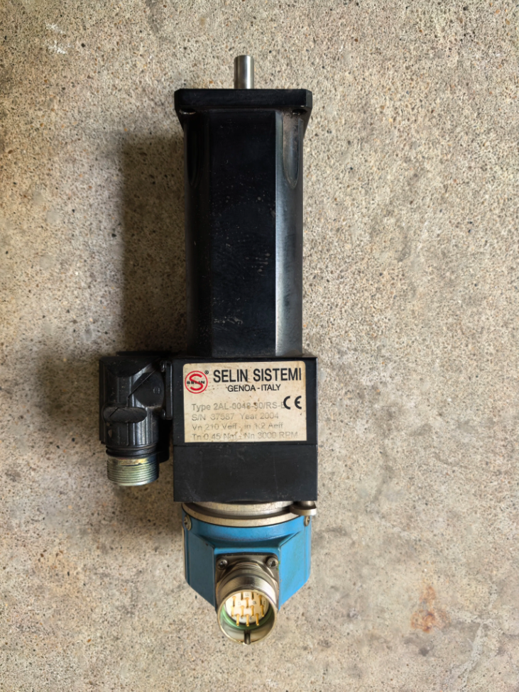

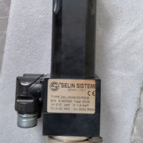
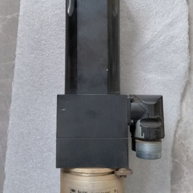
The full standard model designation is 2AL-0048-30/RS-B. Manufactured by Italy-based brand SELIN SISTEMI, it is an industrial low-voltage closed-loop stepper サーボモーター (hybrid servo). This model has been phased out by the original manufacturer; spare parts and second-hand dismantled units dominate the current market supply.
- Digit-by-Digit Model Code Breakdown
| コードセグメント | 意味 |
| 2アル | Main product series: 48mm frame low-voltage closed-loop servo series with flange mounting, designed for compact precision motion control |
| 48 | フレームサイズ & power rating: 48mm flange mounting dimension (compatible with standard NEMA23 mounting holes), rated power approx. 48W |
| 30 | Rated speed specification: 3000 rpm rated speed, high-speed stepper servo design |
| RS | Feedback type: Resolver feedback. Vibration-resistant, oil-proof and wide-temperature tolerant, 過酷な産業環境に適しています |
| B | Structural suffix: Standard Type B flange mounting, standard straight output shaft with keyway, basic version without brake |
- Full List of Core Specifications
電気仕様
| パラメータ項目 | 仕様値 |
| 供給電圧 | DC24V (operating range: 20~28V DC) |
| Rated Phase Current | 約. 1.6 あ |
| Holding Torque | 約. 1.6 N・m |
| 定格速度 | 3000 回転数 |
| Step Angle | 1.8° (200 steps per revolution; higher positioning accuracy achievable via closed-loop microstepping) |
| Position Feedback | リゾルバ, no glass code disc, impact and vibration resistant |
| 制御モード | Pulse/Direction control; closed-loop position correction realized with dedicated matching driver |
| 絶縁クラス | クラスB |
機械式 & Mounting Specifications
| パラメータ項目 | 仕様値 |
| Flange Dimension | 48mm × 48mm (compatible with NEMA 23 mounting holes) |
| シャフト径 | 8mm standard keyway shaft |
| Motor Body Length | 約. 110mm (including connectors) |
| 侵入保護評価 | Shaft end IP65, motor body IP40 |
| 取付方法 | Vertical flange mounting, compatible with 35mm DIN rail-mounted drivers |
| Total Weight | 約. 0.8 kg |
Ⅲ. コア機能 & 動作原理
- Closed-Loop Stepper Servo Architecture
This motor falls under the hybrid servo (closed-loop stepper) category. Essentially, it adds resolver position feedback to a conventional stepper motor:
In open-loop mode, it operates under stepper logic with low cost and high low-speed torque;
In closed-loop mode, it compares command position and actual position in real time to automatically compensate step loss, delivering positioning accuracy close to standard servo motors and eliminating the step missing issue of traditional steppers.
- Environmental Advantages of Resolver Feedback
Compared with conventional optical encoders, resolver systems offer superior adaptability to harsh working conditions:
Free of fragile components such as glass code discs and light-emitting diodes; impact and vibration resistance improved by 3 に 5 回;
Wide temperature tolerance (-40℃~+120℃), unaffected by oil stains and dust, ideal for machine tools, on-board equipment and outdoor machinery.
- Low-Voltage Power Distribution Compatibility
24V DC power supply directly matches standard 24V power systems in industrial control cabinets. No extra high-voltage power distribution or high-voltage protection is required, lowering wiring and system integration costs.
- Matching Equipment & 配線説明書
- Matching Driver: Must be paired with SELIN SISTEMI low-voltage servo drivers of the same series, supporting two control modes: Pulse/Direction and analog speed control, directly connectable to PLCs and motion controllers.
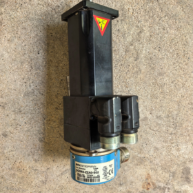
- インターフェースの定義: Two separate circular aviation connectors at the motor tail: one for power lines (電源 + phase windings) and one for feedback lines (resolver signals).
- 配線上の注意:
Shielded cables must be used for resolver signal wires and routed away from power cables to avoid electromagnetic interference;
Sufficient power supply margin is required to prevent voltage drop at startup that causes step loss;
EMC protection must be implemented around inductive loads to avoid signal interference to the resolver.
- 典型的なアプリケーションシナリオ
Small CNC engraving machines, feed axes of CNC lathes, drilling stations
仕分け, transferring and precision positioning stations on automated production lines
Low-load motion axes for semiconductor packaging and electronic SMT equipment
On-board automation and outdoor industrial equipment (leveraging the resolver’s superior environmental resistance)
High-speed narrow-stroke motion axes for textile and packaging machinery
- Fault Maintenance & 代替ソリューション
一般的な障害 & トラブルシューティング
This discontinued legacy model typically presents the following on-site failures:
| 故障現象 | Common Root Cause | Recommended Solutions |
| Driver reports encoder fault | Broken resolver winding, oxidized or loose connector pins | Measure winding resistance of the resolver, clean connector pins, replace resolver assembly |
| Abnormal noise and vibration during motor operation | Worn bearings, demagnetized rotor magnets | Replace bearings of identical specifications, test back EMF to judge magnet status |
| Step loss and inaccurate positioning under load | Mismatched driver parameters, undercurrent setting | Re-tune driver current and microstepping parameters, check if load exceeds rated capacity |
Alternative Selection Schemes
スキーム 1: Same Architecture Functional Replacement (Minimum Modification)
Domestic closed-loop stepper servos with 48mm frame size, nearly compatible mounting holes. Only the motor and driver need to be replaced without modifying control logic:
Leadshine 57-series closed-loop steppers (optional 1000-line encoder/resolver)
Yako YK2-series closed-loop servos with equivalent power rating
スキーム 2: Upgrade to Full Servo (Performance Improvement)
Replace with general low-voltage servo motors for comprehensive upgrades in torque, speed and accuracy; driver replacement and control parameter adjustment are required simultaneously:
Delta B2L series 100W low-voltage servos
HCFA X3 series 100W servo motors
スキーム 3: Original Manufacturer Same-Series Replacement
New SELIN SISTEMI 2AL-E series models with identical specifications, fully compatible mounting dimensions and support for more communication buses. Matching new-generation drivers are required.
- Shaft End Specifications: 意味 & 詳細パラメータ
Shaft end specifications refer to the complete geometric dimensions, tolerance grades, connection forms and surface treatment standards of the motor output shaft. They serve as the core interchangeability basis for mechanical connection between the motor and loads (couplings, lead screws, pulleys).
The 2AL-0048-30/RS-B adopts a standard Type B straight solid shaft with flat key connection, the most widely used shaft form in industrial automation. Detailed parameters are listed below:
| パラメータ項目 | 仕様値 | 説明 |
| シャフトの種類 | Single-end solid straight shaft | Coaxial front output, no reduction gear, hollow bore or spline |
| シャフト径 | φ8 mm, tolerance h6 | Clearance fit, compatible with standard coupling inner bores per national/European standards, smooth assembly and guaranteed coaxiality |
| Shaft Extension Length | 20 mm | Effective fitting length from flange face to shaft tip |
| Flat Key Specification | 3 mm (幅) × 1.3 mm (深さ), key length 16 mm | Complies with standard flat key GB/T 1096 3×3×16; torque transmitted via key side faces to prevent load slipping and rotation loss |
| Central Thread at Shaft End | M4 internal thread with 6mm effective depth | For mounting axial retaining rings and lock washers to limit axial displacement of loads |
| Shaft End Chamfer | C1 (1×45°) | Guides coupling installation and avoids scratching shaft seals and coupling inner walls |
| Shaft Material & 処理 | Quenched and tempered 45# steel with black oxide finish | Moderate hardness, rust-proof and wear-resistant, suitable for long-term industrial operation |
| Shaft Seal Configuration | Contact-type skeleton oil seal | Blocks dust and oil from entering the bearing chamber; shaft end IP54 ingress protection rating |
> 補足: This shaft end follows a universal industry standard, mechanically interchangeable with Type B shafts of most 48-frame stepper and small servo motors. No modification to couplings or load-side structures is needed when replacing motors of the same specification.
- 構造仕様: Full Definition of Suffix “-B”
The suffix -B at the end of the model is the standard base structural code for the SELIN 2AL series, fully defining all mechanical forms of the motor from flange and body to internal configurations across six dimensions:
- Mounting Flange Structure
Standard square flange with 48mm side length, IECに準拠 48 frame standard
取付穴: 4 through holes of φ4.5 mm, diagonal center distance 40 mm, fixed with M4 bolts
Precision-machined flange end face with end face runout ≤0.02 mm to ensure coaxiality with load installation and reduce operating vibration and noise
- Motor Body & Bearing Configuration
Standard-length motor body with lamination thickness corresponding to 1.6 N·m holding torque
Dual front and rear deep groove ball bearing support: front bearing bears major radial force and minor axial force; rear bearing assists rotor positioning
Stretch aluminum alloy housing with black anodized surface, balancing heat dissipation and lightweight design; total weight approx. 0.8 kg
- ブレーキ & 付属品の構成
No built-in electromagnetic power-off brake: Version B is the base model without shaft locking function after power cut. Suitable for horizontal motion applications where load self-weight can be counterbalanced; not directly applicable for vertical lifting loads.
No additional reduction gearbox or external cooling fan; heat dissipation relies on natural convection via the housing
No customized special interfaces; mass-produced universal version of the full series with maximum spare part interchangeability
- ケーブルコンセント & Interface Structure
Split circular aviation connectors at motor tail: 1 power plug (phase windings + 電源) + 1 resolver feedback plug (Resolver signals)
Side cable routing design saves axial space for compact cabinet wiring
Physical isolation between resolver windings and power lines reduces electromagnetic interference and guarantees position feedback precision
- 侵入保護 & Environmental Rating
Main motor body IP40: Blocks solid foreign objects ≥1mm in diameter, designed for cabinet-mounted installation
Shaft end fitted with skeleton oil seal, IP54 rating: Resists minor splashing oil and dust, applicable to general mechanical workshop environments
- Comparison of Structural Suffixes within the Same Series (To Clarify Positioning of Version B)
| サフィックス | Core Structural Differences |
| あ | Smooth shaft without keyway, fixed only via set screws for light-load low-duty applications |
| B | Standard straight shaft with keyway, ブレーキがありません; the most universal and widely stocked version of the full series |
| C | Equipped with electromagnetic power-off brake, for vertical axes and safety scenarios requiring shaft locking upon power loss |
| D | Hollow shaft design, suitable for special applications such as cable threading and vacuum suction cup routing |
| S | ステンレスシャフト & corrosion-resistant housing for food, humid and corrosive environments |
Ⅲ. Key Operation Reminders
- When used for vertical lifting loads, Version B without brake poses a risk of load dropping after power cut. Replace with Version C with built-in brake or install an external mechanical locking mechanism.
- The shaft end keyway is a standard flat key slot. Never force-fit oversize keys, which will deform the shaft, cause uneven bearing wear and shorten motor service life.
- Ensure full flat contact between the flange face and load mounting surface during installation. Do not force alignment to avoid extra radial force on bearings.
Shaft End Specification Parameters of 2AL-0048-30/RS-B
> 注記: Complete original manufacturer drawings of this model are rarely publicly available. The parameters below are compiled based on SELIN 2AL series Type B shaft standard specifications, universal NEMA 23 (48-フレーム) design standards and measured data from dismantled market units, directly applicable to coupling selection and structural connection design.
| パラメータのカテゴリ | Specific Item | 仕様値 | 許容範囲 / Standard Description |
| Shaft Body | シャフトの種類 | Single-end solid straight output shaft | Coaxial front output, no reduction gear or hollow bore |
| シャフト径 | φ8 mm | Tolerance grade h6 (0/-0.009 mm), clearance fit, compatible with standard coupling inner bores per national standards | |
| Shaft Extension Length | 20 mm | Effective fitting length from flange face to shaft tip, measured deviation ≤±0.2 mm | |
| Shaft End Chamfer | C1 (1×45°) | Guides coupling assembly and prevents scratching of shaft seals and mating component inner walls | |
| Keyway Connection | Flat Key Size | 3 mm (幅) × 3 mm (身長) | Complies with national standard GB/T 1096 Type A standard flat key 3×3×16 |
| Keyway Depth on Shaft | 1.3 mm | Slot width tolerance N9; torque transmitted via key side faces to prevent load slipping | |
| Effective Keyway Length | 16 mm | Keyway centered, 2 mm distance from shaft tip | |
| Axial Fixing | Central Thread at Shaft End | M4 internal thread | 6mm effective thread depth for mounting axial retaining rings and lock washers to restrict load axial displacement |
| 材料 & 保護 | Shaft Material | High-quality 45# carbon steel | Quenched and tempered, black oxide anti-rust finish, hardness HB220~250 |
| Shaft Seal Configuration | Contact-type skeleton oil seal | Shaft end IP54 ingress protection, blocks dust and splashing oil from entering bearing chambers |
Supplementary Explanations
- 互換性: This Type B shaft is a universal standard for NEMA 23 stepper and servo motors, fully interchangeable with standard shafts of domestic brands including Leadshine, Yako and Moons. No modification to couplings or load structures is required when replacing motors of the same frame size.
- Measurement Verification: Measured data from dismantled units matched to Bystronic laser equipment aligns with the table above with no customized shaft diameter alterations.
- 予防: The h6 tolerance shaft diameter is a loose fit; never hammer couplings into place. Do not widen the keyway or install non-standard keys to avoid shaft deformation and uneven bearing wear.
 8-Port Industrial Layer 2 Hub")


")
NH42-63-318x560.png "CHINT PC型自動切替スイッチ (ATS)NH42-63/4SZ")


