 コンタクタ,サーキットブレーカー,センサー,エンコーダ,PLC,コンバータ

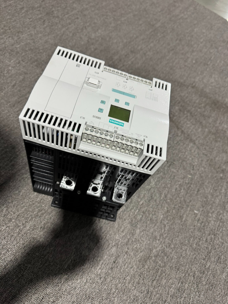

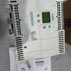
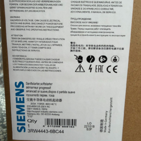
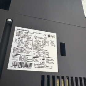
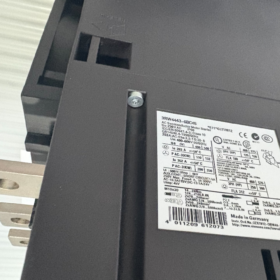
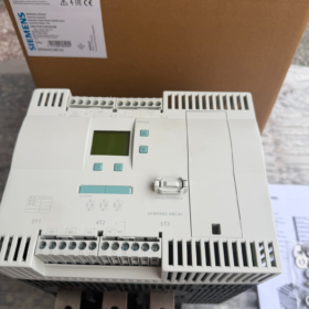
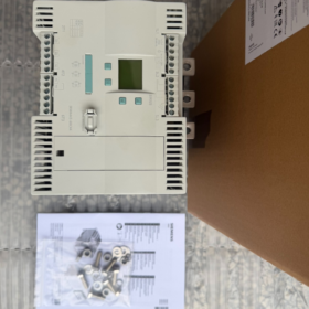
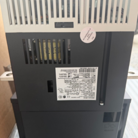
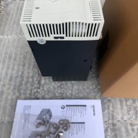
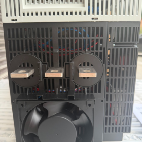
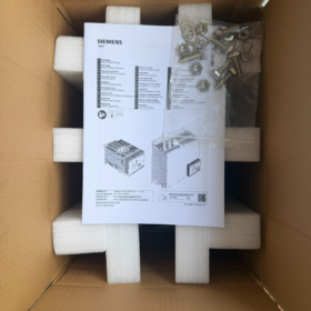
MLFB Order Code Breakdown
3RW 44 43 6 B C 4 4
- 3RW: SIRIUS soft starter product series
- 44: High-performance built-in bypass 3-phase fully controlled ソフトスターター (independent thyristor regulation per phase, integrated bypass contactor as standard)
- 43: サイズコード, 定格電流 203 で 40 °C for standard loads
- 6: Control circuit terminal type = screw terminals; main circuit connected via copper busbars
- B: Integrated bypass contactor (2/3-phase bypass for zero loss during steady-state operation)
- C: Independent 3-phase thyristor control (full 3-phase control to balance 3-phase currents)
- 4: Control supply voltage Us = AC 230 V
- 4: Main circuit operating voltage Ue = AC 200~460 V
- コアの電気パラメータ (40 ℃, クラス 10 Standard Load)
| アイテム | パラメータ値 |
| Rated current for standard wiring (motor directly connected to soft starter) | 203 あ |
| Matched motor power at 400 V | 110 kW |
| Rated current for inside-delta connection (motor windings split into two branches) | 352 あ |
| Matched motor power at 400 V for inside-delta wiring | 200 kW |
| 主回路電圧範囲 | AC 200~460 V (50/60 Hz) |
| 制御電源 | 交流 230 V±10% |
| Phase control mode | Anti-parallel thyristors per phase with independent regulation |
| 標準機能 | Integrated bypass contactor to bypass thyristors during running |
| Standard overload trip class | クラス 10; クラス 10/20/30 configurable manually |
| 保護機能 | 位相損失, phase unbalance, モーターの過負荷, 過熱, thyristor short-circuit, start timeout, earth fault detection |
| Communication expansion | Profibus DP compatible (requires 3RW4900-0KC00 communication module) |
| 重さ | 約. 11.2 kg |
| Country of origin | ドイツ |
Ⅲ. ロードマッチング & Selection Limits
- 適用荷重
ウォーターポンプ, ファン, ベルトコンベア, エアコンプレッサー, チラー, centrifugal equipment (固定速度, only smooth start/stop required)
- Derating Reference for Heavy-Duty Operation (40 ℃)
クラス 20 頑丈な (頻繁な始動, high starting torque): permissible current 170 あ, matched motor 90 kW
クラス 30 extra heavy duty (ボールミル, 破砕機): permissible current 145 あ, matched motor 75 kW
- Prohibited Operating Conditions
Continuous speed regulation, frequent forward/reverse switching, high-frequency jogging (≥30 times per hour)
- ハードウェア構造 & 配線の説明
- 主回路: Copper busbar terminals; L1/L2/L3 line side input, T1/T2/T3 motor side output; supports standard wiring and inside-delta wiring
- 制御回路: Screw terminals for start/stop signals, fault outputs, リセット, external thermistor input
- オペレーターパネル: Built-in LCD display for setting start ramp, initial voltage, ソフトストップ, current limit and protection thresholds
- インストール: Vertical wall mounting; minimum 150 mm top/bottom clearance for heat dissipation; ambient temperature 0~40 °C (derate for temperatures above 40 ℃)
- 製品ライフサイクル & 代替モデル
- 状態: 3RW44 series discontinued (PLM: PM490 end-of-support phase); original manufacturer stops mass production, only stock spare parts available
- Direct OEM Replacement Model (新しいプロジェクトに推奨)
3RW5543-6HA14 (new-generation 3RW55 series, same 203 定格電流, 230 V control supply, 200-460 V main voltage, ネジ端子, 統合されたバイパス)
- Differences Between Old & New Models
Smaller footprint, 消費電力の低減, native Modbus RTU and optimized protection logic for 3RW55
Different mounting cutout dimensions; copper busbars and mounting brackets need modification during cabinet retrofit
- Recommended Matching Protection Devices
- Main Circuit Short-Circuit Protection: Moulded case circuit breaker matched to 110 kW motor circuit
- Specialized Thyristor Protection: aM/gR ultra-fast fuse 500 V 315 あ (mandatory upstream of soft starter, no thyristor short-circuit protection without it)
- Additional Motor Protection: External PTC thermistor connectable to control terminals for winding overtrip protection
Ⅶ. Typical Troubleshooting Matrix
| 故障の症状 | 根本的な原因 | 解決 |
| Overheating alarm during startup | Blocked cooling air duct / ambient temp above 40 ℃ / long-duration heavy-load startup | Clean dust, improve cabinet ventilation, upgrade to higher-rated soft starter |
| Phase loss alarm | Single-phase power loss, loose busbar connection, broken motor winding | Tighten wiring, measure 3-phase input voltage and motor winding resistance |
| Unrestricted starting current, direct full voltage output | Broken-down thyristors, welded bypass contactor contacts | Disconnect power supply to test thyristors; replace bypass contact module |
| Startup timeout trip | Too low initial voltage, seized mechanical load, insufficient ramp time | Increase initial voltage, inspect mechanical load, extend start ramp time |
VIII. 主な利点
- Independent 3-phase voltage regulation; eliminates 3-phase current unbalance common in 2-phase soft starters, extending motor bearing service life
- Integrated bypass eliminates thyristor power loss during steady operation, delivering over 98% energy saving vs non-bypass models
- Supports soft stop and pump stop water hammer suppression, ideal for water supply, drainage and HVAC systems
- Comprehensive integrated motor protection, eliminating the need for separate thermal overload relays
Full Dimension Specifications of シーメンス 3RW4443-6BC44
- Overall Equipment Dimensions (幅×高さ×奥行き, ユニット: mm)
210 (幅) × 230 (身長) × 298 (深さ)
- Mounting Cutout & Fixing Dimensions
- Horizontal center distance between mounting holes: 167 mm
- Vertical center distance between mounting holes: 190 mm
- Fastener specification: M8ボルト, 締め付けトルク 15 N・m
- Cabinet panel cutout minimum reserved width ≥210 mm, height ≥230 mm
Ⅲ. Mandatory Minimum Cabinet Clearance for Heat Dissipation (Vertical Wall Mount)
Top clearance: ≧100mm
Bottom clearance: ≥75 mm
Side clearance (multiple units side-by-side): ≥5 mm
Equipment rear surface to cabinet backplate: direct contact permitted
- Outer Carton Dimensions (倉庫保管 & Logistics Reference)
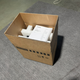
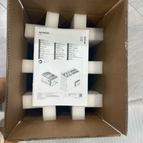
348 × 433 × 394 mm, net weight 11.22 kg
- 補足事項
- 保護クラス: IP00; キャビネット設置のみ
- All 3RW4443 variants (-6BC34/-6BC44/-2BC45) share identical overall dimensions; differences only in control terminals and supply voltage
- Replacement model 3RW5543-6HA14 has a smaller footprint; recalculate cabinet cutout size for retrofits
Complete List & Function Definition of Control Terminals – Siemens 3RW4443-6BC44
This model is equipped with screw-type control terminals, categorized into five groups: 制御電源, デジタル入力, motor PTC temperature sensing, プログラマブルリレー出力, general fault relay.
- Control Power Supply Terminals (Unit Main Supply)
- A1, A2
関数: Main control power supply for soft starter
Model rating: 交流 230 V±10%, 50/60 Hz
Wiring rule: A1 live line L, A2 neutral line N
- PE
Control circuit protective earth terminal; connect to cabinet earth busbar
- L+, L-
Built-in internal DC24 V auxiliary supply for passive digital input switches; 外部の 24 V power supply not required
L+ = DC24 V positive pole; L= DC24 V negative pole (common ground)
- 4 Programmable Digital Input Terminals IN1 / IN2 / IN3 / IN4
論理: Connect one end of switch to L+, the other end to corresponding INx to trigger assigned function; all functions configurable via panel parameters
Factory Default Allocation
IN1: Motor start (Parameter Group 1 forward rotation)
IN2: Unassigned
IN3: Unassigned
IN4: Fault trip reset
All Customizable Functions
Local manual mode, emergency start, low-speed creep, fast emergency stop, fault reset, 3 groups of forward/reverse motor parameter switching
Ⅲ. Motor Winding Temperature Sensing Terminals T1, T2
For external motor PTC thermistor connection (motor overheat protection)
Soft starter trips automatically when winding temperature exceeds threshold
Short-circuit T1 and T2 if no PTC fitted to disable thermal protection
- 3 Independent Programmable Relay Outputs (Passive dry contacts, AC250 V / 5 あ)
Each pair consists of normally-open contacts with fully assignable functions via parameter menu
- 13, 14 出力 1
デフォルト: Motor running signal (closes after startup completion and bypass contactor pull-in)
- 23, 24 出力 2
デフォルト: Unassigned; configurable for bypass status, startup-in-progress, プレアラーム, DC braking, 等.
- 33, 34 出力 3
デフォルト: Unassigned; customizable for all types of equipment status signals
- General Fault Relay Terminals 95, 96, 98 (Global Fault Alarm)
3-pole changeover contact for unified fault signaling, widely used in safety circuits
95: Common terminal COM
95-96: 通常閉 (ノースカロライナ州): conductive when unit healthy; opens upon fault trip
95-98: 通常開 (いいえ): closes when fault occurs, for fault indicator light / alarm horn wiring
Terminal Summary Table
| Terminal Group | Terminal Number | Core Purpose |
| 制御電源 | A1, A2 | AC230 V control voltage input |
| Protective Earth | PE | Control circuit grounding |
| 内蔵 24 V Supply | L+, L- | DC24 V power for digital inputs (ポジティブ / 地面) |
| デジタル入力 | IN1, IN2, IN3, IN4 | Start/stop, リセット, parameter switchover, manual mode etc. |
| PTC Temperature Sensing | T1, T2 | Motor winding overheat thermistor interface |
| リレー出力 1 | 13, 14 | Motor running status (通常は開いています) |
| リレー出力 2 | 23, 24 | Customizable equipment status (通常は開いています) |
| リレー出力 3 | 33, 34 | Customizable equipment status (通常は開いています) |
| Fault Changeover Contact | 95, 96, 98 | Global fault alarm (COM + ノースカロライナ州 + いいえ) |
Supplementary Wiring Guidelines
- Tightening torque for control wires: 1.2~1.5 N·m; wire cross-section 0.75~1.5 mm² copper conductors
- Digital inputs are passive contact type; power solely from internal L+/Lwithout external PLC 24 V電源
- Series the normally closed 95/96 contacts in safety circuit to cut upstream contactor power on fault
- Profibus communication requires separate 3RW4900-0KC00 module with dedicated port (not part of front control terminals)





NH42-63-318x560.png "CHINT PC型自動切替スイッチ (ATS)NH42-63/4SZ")



