
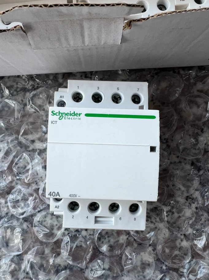

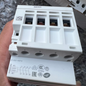


Schneider Electric A9C20844 is a 4-pole, 40A contactor belonging to the Acti9 iCT series, featuring 4 평상시 열려 있음 (4아니요) contacts. It has a coil voltage of 220-240V AC (50헤르츠), is suitable for 400V AC circuits, and can be applied to motor, heating and lighting loads, complying with utilization categories such as AC-1/3/7a.
핵심 매개변수
| 매개변수 | 값 |
| 모델 | A9C20844 |
| 시리즈 | Acti9 iCT |
| Pole Number/Contacts | 4피, 4아니요 (4 Normally Open) |
| Rated Operating Current | 40에이 (AC-7a), 15에이 (AC-7b) |
| Rated Operating Voltage | 400뷔와 (50헤르츠) |
| Control Coil Voltage | 220-240뷔와 (50헤르츠) |
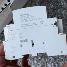
| 정격 절연 전압 | 500뷔와 (50/60헤르츠) |
| Rated Impulse Withstand Voltage | 4kV |
| Making Power Consumption | 53버지니아 (50헤르츠) |
| Holding Power Consumption | 6.5버지니아 (50헤르츠) |
| 장착 방법 | 35mm DIN Rail |
| 치수 (H×W×D) | 85mm×54mm×60mm |
| 보호 등급 | IP20 |
| 기계적 수명 | 1,000,000 운영 |
Key Features
- 응용 시나리오: Suitable for motor control, resistive heating, lighting and other loads, supporting remote and self-holding control.
- Utilization Categories: Complies with IEC 60947-4 (AC-1/AC-3) 그리고 IEC 61095 (AC-7a) 표준.
- Safety and Indication: With an impulse withstand voltage of 4kV, it is equipped with a trip indication window for easy status monitoring.
- Installation and Connection: DIN rail mounting with screw terminals ensures reliable wiring.
Selection and Application Points
- 부하 매칭: AC-7a (40에이) is suitable for resistive loads, and AC-7b (15에이) is suitable for lighting loads; for motor control, the current shall be verified according to AC-3 operating conditions.
- Coil Matching: Confirm that the control circuit voltage is 220-240V AC 50Hz to avoid incorrect connection.
- 환경 조건: Operating temperature ranges from -5℃ to +60℃, with IP20 protection class, suitable for installation in distribution cabinets.
- Accessories: Auxiliary contacts and surge suppressors can be configured to enhance control and protection capabilities.
설치 및 유지 관리
- Installation: Fixed on DIN rail, reserve heat dissipation space, and wire the terminals in accordance with torque specifications.
- Maintenance: Regularly check for contact ablation, coil temperature rise and fixing status to ensure reliable operation.
Common Replacement and Compatibility
Intra-series Replacement: Models such as A9C20840 (2피) and A9C20842 (3피) can be used as alternatives, selected based on pole number and current rating.
Cross-series Replacement: For replacement with TeSys D series, it is necessary to verify dimensions, wiring and protection coordination.
Schneider Electric A9C20844 contactor is a 35mm standard DIN rail mounting type. The installation shall follow the process of “Safety Preparation → Mechanical Installation → Electrical Wiring → Inspection and Commissioning”.
- 설치 전 준비
- Safety Confirmation
Disconnect all power supplies of the main circuit and control circuit, and use a voltage tester to confirm no electricity to prevent electric shock.
Confirm that the installation environment meets the requirements: temperature ranging from -5℃ to +60℃, free of corrosive gases, dust and strong electromagnetic interference, with good ventilation.
- Tool and Material Preparation
Tools: Phillips screwdriver, torque wrench (range 0.5~2N·m), wire stripper, 전압 테스터, 500V megohmmeter.
Materials: Schneider Electric A9C20844 contactor, 35mm standard DIN rail, cables with suitable wire diameter, terminal marking plates, insulating tape.
- Product Inspection
Verify that the contactor model (A9C20844) and coil voltage (220-240뷔와) are consistent with the design requirements.
Inspect the appearance: no damage to the housing, no oxidation or ablation of contacts, no deformation of buckles; manually press the contactor’s moving iron core to ensure flexible operation without jamming.
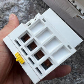
- Mechanical Installation (DIN Rail Fixing)
- Rail Fixing
Fix the 35mm standard DIN rail on the distribution cabinet mounting plate with screws, with a rail levelness deviation ≤1mm/m to ensure firm installation.
Reserve heat dissipation space around the contactor: spacing ≥10mm on the left and right sides, and ≥20mm on the top and bottom sides; avoid close arrangement with heating components (such as fuses and frequency converters).
- Contactor Clamping
Hold the contactor, align its top buckle with the upper edge of the DIN rail, and press downwards.
Press the bottom of the contactor firmly until the bottom buckle clicks into the lower edge of the DIN rail; pull the contactor slightly to confirm no loosening, and then the mechanical fixing is completed.
For disassembly, pry the unlocking slot of the bottom buckle with a flathead screwdriver and lift the contactor upwards to remove it.
III. Electrical Wiring
Schneider Electric A9C20844 has a 4P 4NO (4 Normally Open) structure, with terminals divided into main circuit terminals and control circuit terminals. Wiring must strictly match the wire diameter and torque requirements.
- Terminal Identification Confirmation
| 터미널 유형 | Terminal Marking | 기능 설명 | Suitable Wire Diameter | Torque Requirement |
| Main Circuit Terminal | L1/L2/L3/L4 (Incoming Line), T1/T2/T3/T4 (Outgoing Line) | Connect to 400V AC load circuit | 6~10mm (Copper Core Cable) | 0.8~1.2N路m |
| Control Circuit Terminal | A1, A2 | Connect to 220-240V AC coil power supply | 1.5~2.5mm虏 (Copper Core Cable) | 0.5~0.8N路m |
- Wiring Operation
Wire Stripping: Strip the cable insulation layer to expose the conductor with a length of about 8~10mm to avoid short circuit due to excessive length or poor contact due to insufficient length.
Main Circuit Wiring: Connect the incoming cables to L1-L4 terminals and outgoing cables to T1-T4 terminals; use a torque wrench when tightening the screws to ensure the torque meets the standard and prevent heating caused by loose connections.
Control Circuit Wiring: Connect the control power supply (such as buttons, PLC outputs) to A1 and A2 terminals, no polarity distinction required; if a surge suppressor (such as RC component) needs to be installed, connect it in parallel between A1 and A2 terminals.
Marking: Attach marking plates to all terminals, indicating the circuit names (예를 들어, “Motor 1 Main Circuit”, “Control Circuit Power Supply”) for convenient subsequent maintenance.
- Post-installation Inspection
- Mechanical Inspection
Pull the contactor and cables slightly again to confirm that the contactor is firmly clamped and the cables are not loose.
Manually push the contactor’s moving iron core to simulate making/releasing actions; the contacts should have good contact without jamming or abnormal noise.
- Electrical Inspection
Use a 500V megohmmeter to measure the insulation resistance between main circuit terminals and between main circuit and housing; the resistance value should be ≥10MΩ to confirm no short circuit.
Inspect the control circuit wiring to confirm that the coil voltage is consistent with the power supply, without incorrect or missing connections.
- Commissioning
- No-load Commissioning
Close the control circuit power supply, press the control button, and observe whether the contactor closes smoothly without obvious noise; release the button, and the contactor should release quickly.
Repeat the making/releasing operation 5~10 times to confirm reliable operation.
- Load Commissioning
Close the main circuit power supply, connect the load (모터와 같은, heaters) step by step, and run for 1~2 hours.
Use a thermometer to detect the temperature of the contactor housing and terminals; the temperature rise should be ≤40K (ambient temperature +40℃ ≤ housing temperature), without peculiar smell or smoke.
Installation Precautions
- It is strictly prohibited to perform installation, wiring or disassembly operations when the equipment is energized.
- The cable wire diameter must match the rated current; direct wiring with aluminum core cables is prohibited (copper-aluminum transition terminals shall be used).
- The contactor shall be installed vertically on the DIN rail; horizontal or inverted installation is prohibited, otherwise the operation reliability will be affected.
- When multiple contactors are installed side by side, attention should be paid to the temperature rise caused by the superposition of load currents; if necessary, increase the spacing or install cooling fans.


")


NH42-63-318x560.png "CHINT PC형 자동절환스위치 (ATS)NH42-63/4SZ")

")

