 Contactor,circuit breaker,solar inverter,electric meter,solar batteries

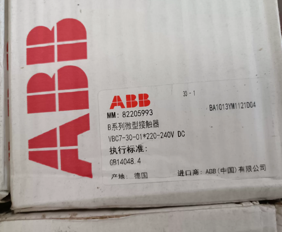

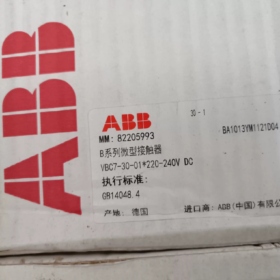
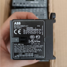
- Model Interpretation
| Model Segment | Description |
| ABB | Brand Logo |
| VBC7 | Series Name: VBC7 Series Miniature Reversing Contactor (equipped with mechanical interlock, for motor forward and reverse rotation control) |
| 30 | Main Contact Configuration: 3-pole Normally Open (3NO) |
| 1 | Auxiliary Contact Configuration: 1 Normally Closed (1NC) |
| 220-240V DC | Coil Control Voltage: DC 220-240V |
| * | Special Version Identifier (may be a customized or market-specific version) |
Full Model: VBC7-30-01-05 (standard model, corresponding to 220-240V DC coil)
- Core Technical Parameters
- Basic Electrical Parameters
| Parameter Item | Value | Remarks |
| Rated Current of Main Contacts | 16A (AC-3) / 20A (AC-1) | AC-3: Control of 5.5kW three-phase motor at 400V |
| Rated Operating Voltage | 690V AC | Complies with IEC 60947-4-1 standard |
| Coil Control Voltage | 220-240V DC | Wide voltage range, allowing 卤15% fluctuation |
| Coil Power Consumption | Pick-up: approx. 5W | DC coil operates with no noise or humming |
| Holding: approx. 5W | ||
| Mechanical Service Life | 10 million operations | Under standard operating conditions |
| Electrical Service Life | AC-1: 1 million operations | Under rated load |
| AC-3: 100,000 operations |
- Performance Indicators
| Parameter Item | Value | Applicable Conditions |
| Mechanical Interlock | Built-in reliable mechanical interlock | Prevents simultaneous closing of forward and reverse contactors |
| Overvoltage Protection | Built-in surge suppression diode | Protects coil and control circuit |
| Switch Position Indication | Visual position marking | Facilitates fault diagnosis and status confirmation |
| Insulation Class | Class F | Complies with IEC standards |
| Protection Rating | IP20 | Must be installed inside control cabinet |
- Environmental and Installation Parameters
| Parameter Item | Value | Standard/Remarks |
| Operating Temperature | -25℃~+60℃ | Storage Temperature: -40℃~+85℃ |
| Mounting Method | 35mm DIN rail mounting / screw mounting | Space-saving and easy to integrate |
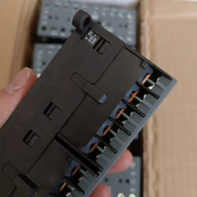
| Terminal Type | Screw terminals | Suitable for 22-10 AWG stranded wires |
| Weight | Approx. 250g | Compact design with light weight |
III. Functional Features
- Dedicated for Reversing Control: Built-in mechanical interlock ensures that forward and reverse contactors cannot be closed simultaneously, ensuring safety and reliability.
- Quiet Operation: DC coil design eliminates the humming noise common in AC contactors, enabling silent operation.
- Wide Voltage Adaptability: The coil supports a wide voltage range of 220-240V DC, adapting to different power supply conditions.
- Overvoltage Protection: Built-in surge suppression diode effectively protects the coil and control circuit from voltage spikes.
- Status Indication: Clear switch position indication facilitates on-site operation and fault diagnosis.
- Flexible Installation: Supports both DIN rail and screw mounting methods, adapting to various control cabinet layouts.
- High Reliability: With a mechanical service life of up to 10 million operations and long electrical service life, it is suitable for frequent operation scenarios.
- Application Scope
- Motor Control: Forward and reverse rotation control of three-phase asynchronous motors, such as:
Small conveyors and hoists
Fans and pumps (requiring reversible operation)
Packaging machinery and printing machinery
- Industrial Automation:
Control of auxiliary equipment in production lines
Output actuator for small PLC control systems
Equipment interlock control circuits
- Commercial and Building Applications:
Fan control in air conditioning systems
Elevator door motors and small lifting platforms
Automatic door and rolling shutter door control
- Other Applications:
Control of battery-powered equipment (compatible with DC coil)
Auxiliary circuits of solar inverters
Small load control in marine and rail transit systems
- Selection Suggestions
- Load Matching:
AC-3 loads (motor starting/operation): Max. 5.5kW (400V), rated current 16A
AC-1 loads (resistive loads): Max. 20A, 690V
- Control Voltage Confirmation: Ensure the coil voltage matches the system DC power supply (220-240V DC).
- Auxiliary Contact Requirements: Standard configuration is 1NC; for more contacts, select the VBC7-30-10 series (1NO) or expansion modules.
- Installation Environment:
Derating is required when the temperature exceeds 40℃ (rated current decreases by 10% for every 10℃ rise)
Additional protective measures are needed in dusty and humid environments
- Accessory Selection:
It is recommended to match with a surge suppressor (built-in for DC coils)
Optional auxiliary contact modules and thermal overload relays (e.g., TA25DU series)
- Alternative Models:
Non-reversing version: BC7-30-01-05 (without mechanical interlock)
Different coil voltages: VBC7-30-01-01 (24V DC), VBC7-30-01-07 (12V DC)
- Troubleshooting
| Fault Phenomenon | Possible Causes | Troubleshooting Methods |
| Contactor fails to pull in | 1. No voltage or low voltage at the coil | 1. Check the control circuit voltage (220-240V DC) |
| 2. Coil burnout | 2. Measure the coil resistance (approx. 10k惟 under normal conditions) | |
| 3. Mechanical jamming | 3. Inspect contacts and mechanical mechanism, and remove foreign objects | |
| Contactor releases immediately after pulling in | 1. Excessive voltage fluctuation | 1. Stabilize the control voltage and check the power supply capacity |
| 2. Poor coil contact | 2. Tighten the coil terminals | |
| 3. Overload protection activation | 3. Check the status of the thermal overload relay | |
| Contact heating/welding | 1. Load current exceeds the rated value | 1. Replace with a contactor of larger capacity or use it with derating |
| 2. Contact oxidation or contamination | 2. Clean or replace the contacts | |
| 3. Frequent overload operation | 3. Inspect the load and eliminate overload causes | |
| Interlock failure | 1. Damage to the mechanical interlock mechanism | 1. Inspect the interlock mechanism and replace if necessary |
| 2. Improper installation leading to interlock release | 2. Reinstall to ensure proper engagement of the interlock mechanism | |
| Severe coil heating | 1. Excessively high voltage | 1. Adjust the control voltage to the rated range |
| 2. Coil short circuit | 2. Measure the coil resistance and replace the damaged coil | |
| 3. High ambient temperature | 3. Improve heat dissipation conditions and reduce the ambient temperature |
VII. Installation and Wiring Key Points
- Before installation, confirm that the coil voltage is 220-240V DC, matching the control power supply.
- For reversing control, ensure that the mechanical interlock of the two contactors (forward/reverse) is correctly installed to prevent phase-to-phase short circuit.
- Main circuit wiring: Connect L1, L2, L3 to the power supply, and T1, T2, T3 to the motor; pay attention to the phase sequence (when switching between forward and reverse rotation).
- Control circuit wiring: Connect coil terminals A1 and A2 to the 220-240V DC power supply; pay attention to polarity (some models have no polarity requirements).
- Auxiliary contact wiring: The 1NC contact can be used for interlock control or status indication; pay attention to the rated current of the contact (usually 5A).
- Installation spacing: Keep a distance of at least 5mm from other components to ensure good heat dissipation.
- Pre-power-on inspection:
Check if the mechanical interlock operates flexibly and reliably
Check if the contacts are in good contact
Check if the coil wiring is correct
ABB VBC7-30-01 Core Parameter and Price Comparison Table with Same Series and Competitor Models
- Comparison of ABB Same Series Models (Core Parameters)
| Parameter Item | VBC7-30-01-05 | VBC7-30-10-05 | BC7-30-01-05 | Difference Description |
| (220-240V DC) | (220-240V DC) | (220-240V DC) | ||
| Type | Miniature reversing contactor | Miniature reversing contactor | Miniature non-reversing contactor | VBC7 with mechanical interlock; BC7 without interlock |
| Main Contacts | 3NO (3-pole normally open) | 3NO (3-pole normally open) | 3NO (3-pole normally open) | Identical |
| Auxiliary Contacts | 1NC (1 normally closed) | 1NO (1 normally open) | 1NC (1 normally closed) | Different auxiliary contact types |
| Rated Current | 16A (AC-3) / 20A (AC-1) | 16A (AC-3) / 20A (AC-1) | 16A (AC-3) / 20A (AC-1) | Identical, suitable for 5.5kW (400V) motor |
| Rated Voltage | 690V AC | 690V AC | 690V AC | Identical |
| Coil Voltage | 220-240V DC | 220-240V DC | 220-240V DC | Identical, DC operation with no noise |
| Mechanical Interlock | Built-in reliable mechanical interlock | Built-in reliable mechanical interlock | None | Exclusive to VBC7 series, preventing simultaneous closing of forward and reverse contactors |
| Surge Protection | Built-in suppression diode | Built-in suppression diode | Built-in suppression diode | Identical |
| Mounting Method | DIN rail / screw mounting | DIN rail / screw mounting | DIN rail / screw mounting | Identical |
| Mechanical Service Life | 10 million operations | 10 million operations | 10 million operations | Identical |
| Electrical Service Life | AC-3: 100,000 operations | AC-3: 100,000 operations | AC-3: 100,000 operations | Identical |
| AC-1: 1 million operations | AC-1: 1 million operations | AC-1: 1 million operations | ||
| Protection Rating | IP20 | IP20 | IP20 | Identical, must be installed inside control cabinet |
| Reference Price | Approx. 380-450 | Approx. 380-450 | Approx. 320-380 | BC7 is slightly cheaper; VBC7-30-01 and 30-10 are similarly priced |
- Comparison of ABB VBC7-30-01 with Competitor Models (Core Parameters + Price)
| Parameter Item | ABB VBC7-30-01-05 | Schneider LC1D18FD | Siemens 3RT2016-1BB41+3RT2016-1BB41 | Selection Suggestion |
| (220-240V DC) | (Reversing, 220V DC) | (Reversing Combination, 220V DC) | ||
| Brand Series | ABB VBC7 Series | Schneider LC1D Series | Siemens 3RT2 Series | – |
| Type | Integrated reversing contactor | Integrated reversing contactor | Dual-contactor combination | ABB/Schneider integrated design saves more space |
| (with mechanical interlock) | (with mechanical interlock) | (external mechanical interlock required) | ||
| Main Contacts | 3NO (3-pole normally open) | 3NO (3-pole normally open) | 3NO+3NO (dual contactors) | Identical |
| Auxiliary Contacts | 1NC | 1NO+1NC | 1NO+1NC (per contactor) | Schneider/Siemens have more abundant auxiliary contacts |
| Rated Current | 16A (AC-3) / 20A (AC-1) | 18A (AC-3) / 25A (AC-1) | 9A (AC-3) / 12A (AC-1) | Schneider has higher rated current, suitable for 7.5kW motor |
| Applicable Motor Power | 5.5kW (400V AC-3) | 7.5kW (400V AC-3) | 4kW (400V AC-3) | Schneider supports higher power |
| Coil Voltage | 220-240V DC | 220V DC | 220V DC | Identical, DC operation with no noise |
| Mechanical Interlock | Built-in, reliable and durable | Built-in, long mechanical service life | External required, increased cost | ABB/Schneider are more convenient to use |
| Surge Protection | Built-in suppression diode | Built-in varistor | Built-in varistor | Identical protection function |
| Mounting Method | DIN rail / screw mounting | DIN rail / screw mounting | DIN rail / screw mounting | Identical |
| Mechanical Service Life | 10 million operations | 10 million operations | 10 million operations | Identical |
| Electrical Service Life | AC-3: 100,000 operations | AC-3: 100,000 operations | AC-3: 100,000 operations | Identical |
| AC-1: 1 million operations | AC-1: 1 million operations | AC-1: 1 million operations | ||
| Protection Rating | IP20 | IP20 | IP20 | Identical, must be installed inside control cabinet |
| Width Dimension | 45mm | 55mm | 45mm*2 (dual contactors) | ABB has the smallest volume |
| Reference Price | Approx. 380-450 | Approx. 420-480 | Approx. 450-520 (dual contactors) | ABB offers the best cost performance |
| Advantages | Integrated design, quiet operation, smallest volume | High rated current, abundant auxiliary contacts | Siemens ecosystem compatibility, strong diagnostic functions | Select according to load power and space constraints |
III. Price and Selection Replacement Summary
- Same Series Replacement Recommendations
| Original Model | Replacement Model | Replacement Reason | Notes |
| VBC7-30-01-05 | VBC7-30-10-05 | Different auxiliary contact type (1NC→1NO) | Confirm auxiliary contact requirements in the control circuit |
| VBC7-30-01-05 | BC7-30-01-05 | Lower price for non-reversing applications | Not suitable for forward/reverse control, no mechanical interlock |
| VBC7-30-01-05 | VBC7-30-01-01 | Different coil voltage (220V DC→24V DC) | Must match the system control power supply voltage |
- Cross-Brand Replacement Recommendations
| Original Model | Optimal Replacement | Alternative Replacement | Replacement Advantages |
| VBC7-30-01-05 | Schneider LC1D18FD | Siemens 3RT2016 Combination | Higher rated current and applicable power |
| VBC7-30-01-05 | ABB VBC7-30-10-05 | Schneider LC1D12FD | Better compatibility with the same brand, no need to adjust installation dimensions |
- Key Selection Points
- Load Matching: Select the corresponding rated current for standard loads; for heavy-duty applications, it is recommended to choose one size larger (e.g., VBC7→Schneider LC1D25FD).
- Control Voltage: Ensure the coil voltage matches the system DC power supply (220-240V DC).
- Auxiliary Contacts: Select 1NC/1NO or versions with more contacts according to the control circuit requirements.
- Installation Space: Integrated reversing contactors (ABB VBC7/Schneider LC1D) save about 40% space compared to dual-contactor combinations.
- Cost Control: Same-brand replacement has the lowest cost; cross-brand replacement needs to consider installation adaptability and system compatibility.


")

NH42-63-318x560.png "CHINT PC-type automatic transfer switches (ATS)NH42-63/4SZ")


