 Contactor,circuit breaker,solar inverter,electric meter,solar batteries

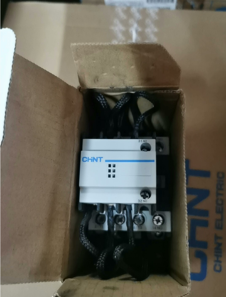

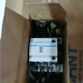
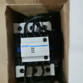
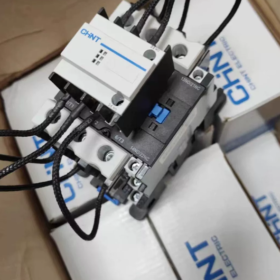
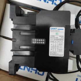
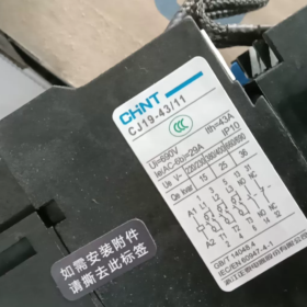
Chint CJ19-3211 Contactor
Chint CJ19-3211 is an AC contactor belonging to the CJ19 series, which is mainly used for switching capacitors in low-voltage reactive power compensation equipment.
Basic Parameters
Rated Voltage: Available in specifications such as 220V and 380V.
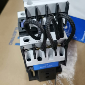
Rated Current: 32A.
Coil Frequency: 50/60Hz.
Arc-extinguishing Medium: Air-type.
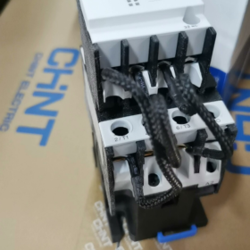
Auxiliary Contacts: Including 1 normally open (NO) auxiliary contact and 1 normally closed (NC) auxiliary contact.
Structural Features: It adopts a direct-acting double-breakpoint structure, and the contact system is divided into upper and lower layers. The upper layer is equipped with pre-charging contacts and three pairs of current-limiting resistors to form a current-limiting device, while the lower layer consists of working contacts. During closing, the current-limiting device is connected first; several milliseconds later, the working contacts are closed. The magnet in the pre-charging contacts is released under the reaction force of the spring, disconnecting the current-limiting resistors to ensure the normal operation of the capacitor.
Scope of Application: It is mainly used in power lines with AC 50Hz (or 60Hz) and rated working voltage up to 690V, for switching low-voltage shunt capacitors in low-voltage reactive power compensation equipment.
Operating Conditions
Ambient Air Temperature: -5℃ ~ +40℃, with the average value not exceeding +35℃ within 24 hours.
Altitude: Not exceeding 2000m.
Installation Conditions: The inclination angle between the mounting surface and the vertical plane shall not be greater than ±5°. It should be installed in a place free from significant shaking, impact and vibration.
Product Certification: It has obtained CCC certification and complies with relevant national and international standards, such as GB/T 14048.4 and IEC/EN 60947-4-1.
Installation Steps of Chint CJ19-3211 Contactor
Chint CJ19-3211 is a dedicated contactor for switching low-voltage capacitors. Its installation must comply with electrical equipment installation specifications and take into account the structural characteristics of its current-limiting contacts. The specific steps are as follows:
- Pre-installation Preparation
- Specification and Appearance Inspection
Confirm that the contactor model is CJ19-3211, and the rated coil voltage (e.g., AC 220V/380V) matches the voltage of the control circuit.
Check that the shell is free from cracks and deformation, the contacts are free from oxidation and ablation, the auxiliary contacts (1 NO and 1 NC) move flexibly, and the terminals are not loose.
- Tool and Accessory Preparation
Tools: Phillips/flathead screwdriver, crimping tool, torque wrench, wire stripper, voltage tester pen.
Accessories: Matching fixing bolts (M4/M5), copper lugs (matching the wire diameter of the main circuit), insulating tape, heat shrink tube.
- On-site Condition Confirmation
The installation location must meet the operating conditions: ambient temperature of -5℃ ~ +40℃, free from corrosive gas, dust and severe vibration, and altitude not exceeding 2000m.
Ensure the mounting surface is flat with an inclination ≤ ±5°, and reserve heat dissipation space (no obstacles within 10cm around).
- Safety Protection
Disconnect the main power supply in the installation area, and confirm no voltage with a voltage tester pen before operation to avoid electric shock.
- Fixing the Installation Position
CJ19-3211 adopts bolt-fixed installation and does not support DIN rail installation. The steps are as follows:
- Mark the drilling positions on the mounting panel (preferably a metal plate with thickness ≥ 2mm) according to the dimensions of the mounting holes at the bottom of the contactor.
- After drilling, fix the contactor on the panel with bolts, and tighten with a torque wrench (recommended torque: 2.5~3.5N·m) to ensure the contactor is free from looseness and skew.
- If installed in a distribution cabinet, keep a reasonable distance between the contactor and other components (e.g., fuses, capacitors), and arrange the main circuit and control circuit wiring separately to avoid electromagnetic interference.
III. Wiring Operation
(I) Main Circuit Wiring (Core, for Capacitor Switching)
The main circuit terminals of CJ19-3211 are 3-pole input and output, with current-limiting contacts + current-limiting resistors on the upper layer and working contacts on the lower layer. The power terminal and load terminal must be strictly distinguished during wiring:
- Wire Diameter Selection: The rated current of the main circuit is 32A, and 4mm² copper core wire is recommended. The wire diameter should be appropriately increased if the wire is too long.
- Wiring Method
Power terminal (upper terminal): Connect to three-phase power supply (or single-phase power supply, depending on the capacitor type). Strip the wire insulation layer (about 8~10mm), crimp a copper lug, insert it into the terminal, and tighten the screw (torque: 2~2.5N·m) to ensure the wire is not loose.
Load terminal (lower terminal): Connect to low-voltage shunt capacitors. Note that the wiring phase sequence of the capacitor should be consistent with the power supply; reverse connection is strictly prohibited.
After wiring, gently pull the wire to confirm no detachment, and wrap the exposed wiring parts (if any) with insulating tape or heat shrink tube.
(II) Control Circuit Wiring (Coil + Auxiliary Contacts)
- Coil Wiring
Locate the coil terminals (usually marked as A1 and A2) on the side of the contactor, and connect to the control power supply according to the rated coil voltage.
The control circuit should be connected in series with a fuse (recommended rated current: 2~3A) and a control switch (e.g., button, relay contact) to prevent coil burnout due to short circuit.
- Auxiliary Contact Wiring
The auxiliary contacts are 1 normally open (NO) and 1 normally closed (NC) with clear terminal markings, which can be connected as required:
Normally open contact: Used for contactor pull-in signal feedback and circuit interlock control.
Normally closed contact: Used to prevent repeated switching of capacitors and interlock with other components.
The rated current of auxiliary contacts is relatively small (usually ≤ 5A), so wires of 1.5mm² or below should be used. Tighten the terminal screws after wiring.
- Post-installation Inspection and Commissioning
- Static Inspection
Re-tighten all terminals to confirm no wrong or missing connections in the main circuit and control circuit, and no wire damage.
Manually press the contactor’s moving iron core to check that the contacts engage and release smoothly without jamming.
- Power-on Commissioning
Close the control circuit power supply, operate the control switch, and observe that the contactor pulls in smoothly without abnormal noise.
After pull-in, use a voltage tester pen to detect whether the load terminal of the main circuit is live, confirming good contact of the contacts; when the control power supply is disconnected, the contactor should release quickly.
If a capacitor is connected, observe that there is no obvious arc during switching, and the capacitor operates normally (no bulging or abnormal noise).
- Safety Precautions
- Installation and commissioning must be performed by certified electricians, strictly complying with the Code for Installation of Low-Voltage Electrical Installations (GB 50254).
- Capacitors must be discharged before switching; closing with charge is strictly prohibited to avoid contactor damage caused by inrush current.
- After installation, post warning signs near the contactor, indicating parameters such as coil voltage and rated current.
- Regularly inspect the contact status and wiring tightness every 6 months, and clean dust in a timely manner to ensure stable operation of the equipment.


")

NH42-63-318x560.png "CHINT PC-type automatic transfer switches (ATS)NH42-63/4SZ")


