 Contactor,circuit breaker,solar inverter,electric meter,solar batteries


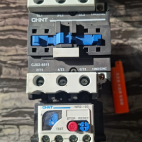
Technical File of Chint CJX2-6511 + NR2-93
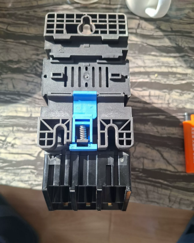
Chint CJX2-6511 + NR2-93 is a standard electromagnetic starter combination, consisting of a CJX2-6511 AC contactor and an NR2-93 thermal overload relay. It is mainly used for remote control, overload and phase failure protection of AC motors, and is widely applied in industrial automation and electrical control systems.
- Model Interpretation
| Component | Model | Meaning |
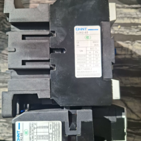
| Contactor | CJX2-6511 | CJX2: Series code (based on Schneider LC1-D technology) |
| 65: Rated current of main contacts is 65A | ||
| 11: Auxiliary contact configuration (1 normally open + 1 normally closed) | ||
| Thermal Overload Relay | NR2-93 | NR2: Series code |
| 93: Frame size is 93A (adjustable current range: 23-93A) | ||
| /Z: With manual/automatic reset selection (standard configuration) |
- Core Technical Parameters
- CJX2-6511 AC Contactor
| Parameter Item | Specification Value | Remarks |
| Rated Operational Voltage | 690V AC | 50/60Hz |
| Rated Operational Current | 65A | Under AC-3 utilization category and 380V condition |
| Rated Insulation Voltage | 690V | – |
| Rated Impulse Withstand Voltage | 6kV | – |
| Control Coil Voltage | 24V/36V/110V/220V/380V AC | Optional, 220V/380V are common choices |
| Main Contact Configuration | 3NO (3 Normally Open) | For making and breaking the main circuit |
| Auxiliary Contact Configuration | 1NO + 1NC | For interlocking of control circuits |
| Mechanical Life | ≥ 10 million operations | – |
| Electrical Life | ≥ 1 million operations | Under AC-3 utilization category |
| Mounting Method | Screw mounting / 35mm standard DIN rail | Compatible with DIN rail |
| Ambient Temperature | -5℃ ~ +40℃ | 24-hour average temperature ≤ +35℃ |
- NR2-93 Thermal Overload Relay
| Parameter Item | Specification Value | Remarks |
| Rated Operational Voltage | 690V AC | 50/60Hz |
| Frame Size | 93A | – |
| Adjustable Current Range | 23-32A, 30-40A, 37-50A | Multiple specifications available, matched with 65A contactor |
| 48-65A, 55-70A, 63-80A | ||
| 80-93A | ||
| Trip Class | 10A | Overload protection characteristic (tripping time is 2-10 seconds at 10 times the rated current) |
| Protection Function | Overload protection + phase failure protection | Three-phase bimetallic strip structure |
| Reset Method | Manual/automatic selectable | Standard configuration is /Z type |
| Mounting Method | Plug-in mounting with CJX2 contactor | Can be mounted independently |
| Ambient Temperature Compensation | Yes | Ensures protection accuracy under different ambient temperatures |
III. Functional Features
- Features of CJX2-6511 Contactor
High-performance Contacts: Silver alloy contacts with excellent conductivity, strong arc erosion resistance and long service life.
Low-noise Design: Optimized electromagnetic system to reduce noise during pull-in and release.
Modular Structure: Expandable auxiliary contacts for flexible installation.
Safe and Reliable: Complies with GB/T 14048.4 and IEC/EN 60947-4-1 standards, with short-circuit protection coordination capability.
Wide Voltage Adaptability: Control coil is compatible with multiple voltage levels to meet the requirements of different control circuits.
- Features of NR2-93 Thermal Overload Relay
Comprehensive Protection: Provides both overload and phase failure protection to prevent motor burnout due to phase loss operation.
Temperature Compensation: Maintains stable protection characteristics when ambient temperature changes.
Action Indication: Clear trip status indication for easy fault troubleshooting.
Flexible Reset: Manual/automatic reset selection to adapt to different control requirements.
Plug-in Mounting: Perfectly matched with CJX2 contactor for quick installation and space saving.
- Advantages of the Combined System
Integrated Control and Protection: The contactor is responsible for circuit on/off and motor starting, while the thermal overload relay provides overload/phase failure protection, forming a complete control and protection unit.
Standardized Design: Complies with international standards and can be seamlessly integrated with other electrical components.
Easy Maintenance: Modular structure allows easy component replacement and reduces maintenance costs.
- Application Scope
- Motor Control: Suitable for frequent starting, stopping, forward and reverse rotation control of three-phase AC motors with power below 30kW (380V).
- Industrial Equipment: General machinery such as fans, water pumps, compressors, conveyors and machine tools.
- Building Electrical Engineering: Central air conditioning systems, fire pumps and elevator control systems.
- Other Applications: Long-distance controlled power transmission and distribution systems, and electrical circuits requiring overload protection.
- Selection Recommendations
- Basic Selection Principles
Contactor Selection: The rated current of main contacts shall be ≥ 1.2-1.5 times the rated current of the motor (inductive load).
Thermal Relay Selection: The adjustable current range shall cover the rated current of the motor (usually set to 0.95-1.05 times the rated current of the motor).
Coil Voltage: Selected according to the power supply of the control circuit, 220V or 380V AC are commonly used.
- Motor Power Matching Table (380V)
| Motor Power | Rated Current | Recommended Thermal Relay Specification | Application Scenario |
| 18.5kW | 37A | NR2-93/Z 37-50A | General load |
| 22kW | 44A | NR2-93/Z 37-50A | General load |
| 30kW | 60A | NR2-93/Z 48-65A | Heavy load, frequent starting |
| 37kW | 74A | NR2-93/Z 63-80A | Derating required (65A contactor is close to the limit) |
- Installation and Usage Precautions
Mounting Direction: The contactor and thermal overload relay can be installed horizontally or vertically, with an inclination angle not exceeding 5°.
Wiring Specifications: The terminals of the main circuit shall be tightened to avoid heating; the cross-sectional area of the control circuit wire shall be ≥ 1.5mm².
Environmental Requirements: Avoid installation in humid, dusty or corrosive gas environments; altitude ≤ 2000m.
Protection Coordination: Must be used with circuit breakers to provide short-circuit protection.
- Troubleshooting
| Fault Phenomenon | Possible Causes | Solutions |
| Contactor fails to pull in | 1. Low coil voltage/phase loss | 1. Check the power supply voltage to ensure it is within 10% of the rated value |
| 2. Burned-out coil | 2. Measure the coil resistance and replace the coil if abnormal | |
| 3. Mechanical jamming | 3. Check the iron core and mechanism to remove foreign objects | |
| 4. Open circuit in control circuit | 4. Check the wiring of the control circuit and repair the open circuit | |
| Loud noise after contactor pulls in | 1. Oil stain/dust on iron core end face | 1. Clean the iron core end face |
| 2. Broken short-circuit ring | 2. Replace the iron core or contactor | |
| 3. Voltage fluctuation | 3. Stabilize the power supply voltage | |
| Contact overheating/ablation | 1. Loose wiring | 1. Tighten the wiring terminals |
| 2. Severe contact wear | 2. Replace the contacts or contactor | |
| 3. Overload | 3. Check the load and replace with a contactor of larger capacity if necessary | |
| 4. High operating frequency | 4. Reduce the operating frequency or select a contactor suitable for AC-4 utilization category | |
| Frequent tripping of thermal overload relay | 1. Excessively small adjustable current | 1. Adjust the adjustable current to the rated current of the motor |
| 2. Motor overload | 2. Check the motor load and eliminate faults | |
| 3. Phase loss operation | 3. Check the wiring of the main circuit and repair the phase loss | |
| 4. High ambient temperature | 4. Improve ventilation conditions and reduce the ambient temperature | |
| Thermal overload relay fails to trip | 1. Excessively large adjustable current | 1. Adjust the adjustable current |
| 2. Damaged heating element | 2. Replace the thermal overload relay | |
| 3. Jammed trip mechanism | 3. Check and repair the trip mechanism |
VII. Substitution and Compatibility
| Component | Chint Model | Compatible/Alternative Model | Remarks |
| Contactor | CJX2-6511 | Schneider LC1-D6511 | Compatible in mounting dimensions and electrical parameters |
| Delixi CDM1-6511 | |||
| ABB A16-30-11 | |||
| Thermal Overload Relay | NR2-93 | Schneider LRD3363 | Similar protection characteristics; attention shall be paid to matching of mounting methods |
| Delixi JR28-93 | |||
| ABB TA25DU |
VIII. Summary
Chint CJX2-6511 + NR2-93 is a cost-effective and highly reliable motor control and protection solution, especially suitable for frequent starting and protection applications of small and medium-sized motors. Its modular design, standardized interface and comprehensive protection functions make it an ideal choice in the field of industrial automation. During selection, it is necessary to choose the appropriate adjustable current specification of the thermal overload relay and the coil voltage of the contactor according to the motor power, rated current and control requirements.
Service Life Details of Chint CJX2-6511 + NR2-93
The service life of the Chint CJX2-6511 + NR2-93 combination shall be comprehensively evaluated from three dimensions: mechanical life (no-load operation times), electrical life (on-load operation times) and actual service life, which is also affected by various factors such as operating conditions and maintenance level.
- Officially Nominal Life Parameters
- CJX2-6511 AC Contactor
| Life Type | Standard Value | Test Condition |
| Mechanical Life | ≥ 10 million operations | Operation under no-load and rated coil voltage |
| Electrical Life | ≥ 600,000 operations (AC-3 utilization category) | Controlling three-phase asynchronous motor under 380V and rated operating current of 65A |
| Electrical Life | ≥ 100,000 operations (AC-4 utilization category) | Frequent starting/reversing/braking conditions with larger current |
- NR2-93 Thermal Overload Relay
| Life Type | Standard Value | Test Condition |
| Mechanical Life | ≥ 1 million operations | Operation under no-load and rated control voltage |
| Electrical Life | ≥ 100,000 operations | Operation of control circuit under rated working conditions |
| Heating Element Life | Long-term stable (about 10 years) | Normal use without frequent overload tripping |
- Key Factors Affecting Service Life
- Factors Affecting Contactor Life
Factor Influence Mechanism Influence Degree Operating Frequency Frequent operation accelerates mechanical wear and contact ablation High (if the frequency is doubled, the life may be halved) Load Type The life of AC-4 load (frequent starting/reversing) is 60-80% lower than that of AC-3 load High Voltage Fluctuation Overvoltage causes coil overheating, and undervoltage causes contact bouncing Medium-High Environmental Conditions Temperature > 40℃, humidity, dust and corrosive gas accelerate aging Medium Mounting Method Non-vertical installation (inclination > 5°) affects heat dissipation and mechanical action Low Maintenance Level Regular cleaning and terminal tightening can extend the service life Medium Factors Affecting Thermal Overload Relay Life
| Factor | Influence Mechanism | Influence Degree |
| Overload Frequency | Frequent overload tripping causes fatigue of bimetallic strips | High |
| Adjustable Current | Excessively small adjustable current leads to unnecessary tripping | Medium |
| Ambient Temperature | High temperature affects protection accuracy and component life | Medium |
| Control Circuit Voltage | Overvoltage causes ablation of control contacts | Low |
III. Life Estimation in Practical Application
- Calculation of Actual Contactor Life (Example)
Assumed working conditions: AC-3 utilization category, 100 operations per day, 300 working days per year
Theoretical electrical life: 600,000 operations
Annual operation times: 100 operations/day × 300 days = 30,000 operations/year
Expected service life: 600,000 ÷ 30,000 = 20 years (ideal working conditions)
If it is AC-4 utilization category with 200 operations per day:
Theoretical electrical life: 100,000 operations
Annual operation times: 200 × 300 = 60,000 operations/year
Expected service life: 100,000 ÷ 60,000 = about 1.7 years (severe working conditions)
- Estimation of Actual Thermal Overload Relay Life
Control Contact Life: With 50 operations per day, the theoretical 100,000 operations can last for about 5.5 years.
Heating Element Life: Under normal use (less than 5 overload trips per month), it can work stably for 8-10 years.
Overall Life: Usually determined by the life of the contactor; the thermal overload relay can be replaced as a wearing part.
- Practical Suggestions for Extending Service Life
- Selection Optimization
The rated current of the contactor shall be ≥ 1.2-1.5 times the rated current of the motor.
For frequent starting/reversing conditions, select AC-4 dedicated contactors or use them with derating.
- Installation and Usage Specifications
Install vertically with good ventilation; control the ambient temperature within -5℃ ~ +40℃.
Keep the control coil voltage stable within ±10% of the rated value.
Set the adjustable current of the thermal overload relay to 0.95-1.05 times the rated current of the motor.
- Maintenance Measures
Regularly clean the contacts and iron core to remove dust and oil stains.
Check the wiring terminals to prevent loosening and heating.
After 3-5 years of operation of the contactor, the contacts and coil can be replaced.
When the thermal overload relay trips frequently, check the motor load and main circuit.
- Summary
Under standard working conditions (AC-3, 100 operations per day), the electrical life of the contactor in the Chint CJX2-6511 + NR2-93 combination is about 20 years, and the mechanical life far exceeds the actual service demand; the overall life of the thermal overload relay is about 10 years. The actual service life mainly depends on the operating frequency, load type and maintenance level, and may be shortened to 1-2 years under severe working conditions. Through reasonable selection, standardized use and regular maintenance, the service life of the equipment can be effectively extended and the replacement cost can be reduced.


")

NH42-63-318x560.png "CHINT PC-type automatic transfer switches (ATS)NH42-63/4SZ")


