

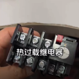
Suitable for overload and phase failure protection of industrial motors; a classic supporting component for motor control.
- Basic Application & Standards
Application: AC 50/60Hz, rated voltage up to 690V, for continuous/intermittent three-phase asynchronous motors, providing overload + differential phase failure protection.
Not suitable for standalone short-circuit protection; must be used with fuses/circuit breakers.
Complies with GB/T 14048.4/5 and IEC 60947-4-1.
Can form a QC36 electromagnetic starter with CJT1 contactors.
Ambient conditions: -5℃ ~ +40℃ (24h average ≤ 35℃), altitude ≤ 2000m, inclination ≤ 5°, no explosive or highly corrosive media.
- Key Technical Parameters
- Frame current: 20A
Setting current available in multiple ranges (0.25–0.35A, 3.2–5A, 10–16A, 14–22A, etc., selected as required).
Trip class: Class 10A
- Auxiliary contacts: 1 NO + 1 NC
AC-15 380V: 0.47A; DC-15 220V: 0.15A
- Wiring specifications:
Main circuit: 1.0–6 mm² (M5 screw)
Auxiliary circuit: 0.5–1 mm² (M3 screw)
- Protection characteristics
1.05 × setting current: cold state, no operation within 2h
1.2 × setting current: hot state, operates within 2h
1.5 × setting current: operates within 2 minutes after thermal equilibrium
7.2 × setting current: cold state, operates at 2s < t ≤10s
Fast differential operation under phase failure
- Functions: temperature compensation, manual/auto reset selectable, test button (manual trip simulation)
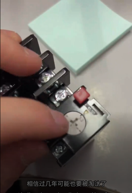
- Structure & Installation
Three-phase bimetallic structure; independent mounting (not DIN‑rail clip type; screw fixing required)
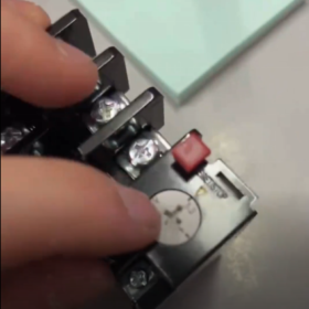
Front panel: setting current adjustment knob, reset button, reset mode switch
Main circuit: three-phase input/output; auxiliary contacts for control circuit
- Selection, Replacement & Usage Notes
- Setting current must match motor rated current (prefer a range that covers the rated value).
- Replacement:
Different current ratings of JR36-20 share interchangeable bases.
Cross-brand equivalents: Delixi JR36-20, People Electrical JR36-20.
Upgrades: CHINT JR-36-20 Thermal Overload Relay.
- Do not operate with wet hands.
Maintain distance ≥50mm from heating components.
Inspect bimetal for deformation after short circuit.
Control circuit must include short-circuit protection.
- Typical Setting Current Sub-Models
| Sub‑Model | Setting Current Range | Suitable Motor Power (380V 3‑phase) |
| JR36-20/10–16 | 10–16A | 5.5–7.5kW |
| JR36-20/14–22 | 14–22A | 7.5–11kW |
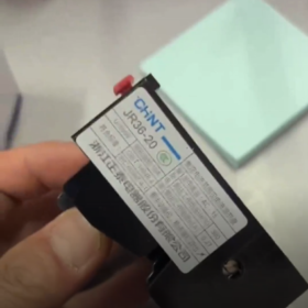
CHINT JR36-20 Thermal Overload Relay
Core Description: Bimetallic thermal overload relay for overload and differential phase failure protection of three-phase asynchronous motors.
Frame current: 20A, trip class: Class 10A.
Not for standalone short-circuit protection; must be used with fuses/circuit breakers.
- Basic Specifications & Standards
| Item | Details |
| Applicable circuit | AC 50/60Hz, rated voltage up to 690V, three-phase system |
| Protected object | Continuous/intermittent three-phase asynchronous motors, against burnout from overload/phase loss |
| Standards | GB/T 14048.4/5, IEC 60947-4-1 |
| Ambient temperature | -5℃ ~ +40℃ (24h average ≤ 35℃) |
| Altitude | ≤ 2000m |
| Installation inclination | ≤ 5° |
| Structure | Three-phase bimetallic type, independent mounting (screw fixed) |
- Key Technical Parameters
2.1 Setting Current & Full Series Sub-Models
| Sub‑Model | Setting Current Range | Suitable Motor Power (380V) |
| JR36-20/0.25-0.35 | 0.25~0.35A | 0.12~0.18kW |
| JR36-20/0.32-0.5 | 0.32~0.5A | 0.18~0.25kW |
| JR36-20/0.45-0.75 | 0.45~0.75A | 0.25~0.37kW |
| JR36-20/0.63-1 | 0.63~1A | 0.37~0.55kW |
| JR36-20/0.8-1.25 | 0.8~1.25A | 0.55~0.75kW |
| JR36-20/1-1.6 | 1~1.6A | 0.75~1.1kW |
| JR36-20/1.25-2 | 1.25~2A | 1.1~1.5kW |
| JR36-20/1.6-2.5 | 1.6~2.5A | 1.5~2.2kW |
| JR36-20/2-3.2 | 2~3.2A | 2.2~3kW |
| JR36-20/2.5-4 | 2.5~4A | 3~4kW |
| JR36-20/3.2-5 | 3.2~5A | 4~5.5kW |
| JR36-20/4-6.3 | 4~6.3A | 5.5~7.5kW |
| JR36-20/5-8 | 5~8A | 7.5~11kW |
| JR36-20/6.3-10 | 6.3~10A | 11~15kW |
| JR36-20/8-12.5 | 8~12.5A | 15~18.5kW |
| JR36-20/10-16 | 10~16A | 18.5~22kW |
| JR36-20/12.5-20 | 12.5~20A | 22~30kW |
| JR36-20/14-22 | 14~22A | 30~37kW |
2.2 Electrical Performance
Trip class: Class 10A (at 7.2× setting current, cold state: 2s < t ≤10s)
Auxiliary contacts: 1 NO + 1 NC, electrically isolated
Wiring: Main 1.0–6 mm² (M5); Aux 0.5–1 mm² (M3)
Terminal marking:
Main: L1/L2/L3 (line), T1/T2/T3 (load)
Control: 95‑96 (NC), 97‑98 (NO)
2.3 Protection Characteristic Curve
| Multiple | Condition | Trip Time |
| 1.05× | Cold | No operation within 2h |
| 1.2× | Hot | Operates within 2h |
| 1.5× | Thermal equilibrium | Operates within 2 min |
| 7.2× | Cold | 2s < t ≤10s |
| Phase failure | Any | Fast differential operation |
- Structural Features & Functions
- Three-phase bimetal with differential design for fast phase‑loss protection
- Continuous setting adjustment via front knob
- Manual / automatic reset (side switch)
- Test button (red) for simulating overload trip
- Temperature compensation reduces ambient influence
- Mechanical trip indicator for fault diagnosis
- Installation & Wiring
4.1 Installation Rules
Independent mounting with M4/M5 screws
Inclination ≤ 5° from vertical
Keep ≥50mm from contactors, transformers and other heat sources
Well ventilated, free from heavy vibration, dust, corrosive gas
4.2 Standard Wiring
- Main circuit: Contactor output → L1/L2/L3 → T1/T2/T3 → Motor stator
- Control circuit: NC (95‑96) in series with contactor coil
- NO (97‑98): For fault alarm, indicator light or PLC input
- Cross‑Brand Replacement & Upgrade
5.1 Direct Replacements
| Brand | Replacement Model | Compatibility |
| Delixi | JR36-20 series | Identical size & parameters |
| People Electrical | JR36-20 series | Same mounting holes |
| Changshu Switch | JR36-20 series | Compatible terminals |
5.2 Recommended Upgrades
| Original | Upgrade | Advantage |
| JR36-20 | CHINT NR2-25 | DIN‑rail mount, more accurate |
| JR36-20 | CHINT NXR-25 | Electronic type, full protection |
- Troubleshooting
| Symptom | Possible Cause | Solution |
| No trip on overload | Setting too high; element damaged; bimetal deformed | Reset to motor rated current; replace unit |
| Unnecessary tripping | Setting too low; high ambient temp; poor ventilation | Adjust setting; improve cooling |
| No phase‑loss protection | Wrong wiring; differential mechanism fault | Check wiring; replace relay |
| Hard to reset | Mechanism jam; not cooled | Wait 5–10 min; retry gently |
| Auxiliary contact failure | Oxidation; loose wiring | Clean contacts; retighten |
- Selection & Usage Tips
- Setting current = motor rated current (max 1.05×)
- Match with CHINT CJT1-20, CJX2-25 contactors for QC36 starter
- Short-circuit protection (fuse/breaker) required in main circuit
- Regular inspection: setting, connections, bimetal condition
- Always inspect relay after short-circuit event


")


NH42-63-318x560.png "CHINT PC-type automatic transfer switches (ATS)NH42-63/4SZ")

")

