 Contactor,circuit breaker,solar inverter,electric meter,solar batteries

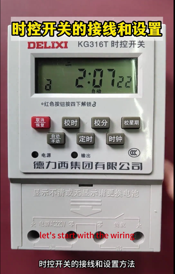

Wiring and Setting of DELIXI Time Control Switch GT316T
The core function of a time control switch is to automatically connect and disconnect the circuit according to the preset time to realize the timed start and stop of equipment (such as lighting, fans, water pumps, and production line auxiliary equipment). The mainstream type for industrial and civil use is the microcomputer time control switch (mainly AC220V, supporting multi-group timing and cyclic control), with dedicated three-phase models and power expansion models available as well. Its core feature is a small rated current of its own contacts (5~10A for conventional models). For high-power or three-phase equipment, it must be used in conjunction with a contactor. The content below is organized in the order of general wiring principles → detailed wiring by scenario → standardized setting of microcomputer models → troubleshooting, which is closely aligned with industrial practical operations, with clear markings of terminals, component matching and safety key points.
Core Premise: Principles of Wiring Safety and Component Matching
- The main power supply must be cut off before wiring; live operation is strictly prohibited. After wiring, check with the continuity gear of a multimeter, and power on only when there is no short circuit.
- The time control switch cannot directly drive high-power/inductive loads (such as motors, water pumps, air conditioners): the contacts of conventional models only support resistive loads ≤5kW (such as lighting and electric heating). Inductive loads, high-power equipment and three-phase equipment must be controlled indirectly through an AC contactor to avoid contact ablation.
- General rules for terminal marking: The terminals of a microcomputer time control switch are all input (power supply terminal) + output (load terminal). The mainstream markings are: `L` (live wire in), `N` (neutral wire in), `L/O` (live wire out), `N/O` (neutral wire out). Some models are simply marked as `IN` (input) and `OUT` (output). Reversing the live and neutral wires is strictly prohibited (although it does not affect the function of some models, it is likely to cause damage to internal components).
- Wire selection: Select 1.5~2.5mm² copper core wires for the control circuit, and match the power circuit wires according to the rated current of the equipment. Crimp cold-pressed terminals at the wiring ends to avoid virtual connection.
- For outdoor/humid scenarios, select a waterproof time control switch (IP65 and above), install it in a distribution box, and take good moisture and dust prevention measures.
- Detailed Wiring of Time Control Switch by Scenario (Mainstream AC220V Microcomputer Model)
The microcomputer time control switch adopts single-phase power supply (even when controlling three-phase equipment, it itself requires AC220V power supply). The wiring is divided into 3 core scenarios, covering 99% of civil and industrial needs. Three-phase time control switches are only niche models; in actual engineering, the combination of “single-phase time control switch + contactor” is used to control three-phase circuits, which is more economical and reliable. The general solutions are highlighted below.
Scenario 1: Single-phase Low-power Resistive Load (Direct Drive Wiring, ≤5kW)
Applicable equipment: Resistive loads such as lighting fixtures, LED screens, electric heaters, and small exhaust fans. No additional components are required, and the time control switch directly connects and disconnects the load circuit.
Terminal matching: Connect the time control switch’s `L` (in) and `N` (in) to the mains AC220V, and `L/O` (out) and `N/O` (out) to the load.
Wiring steps:
- Mains live wire → Time control switch `L` terminal; Mains neutral wire → Time control switch `N` terminal.
- Time control switch `L/O` terminal → Load live wire end; Time control switch `N/O` terminal → Load neutral wire end.
- The protective earth wire of the load is directly connected to the mains earth wire, bypassing the time control switch (the earth wire is for protection only and cannot be connected or disconnected).
Core reminder: This solution is only applicable to resistive loads; connecting inductive loads such as motors and water pumps is strictly prohibited.
Scenario 2: Single-phase High-power/Inductive Load (Indirect Control, ≥5kW)
Applicable equipment: Single-phase water pumps, single-phase motors, air conditioners, high-power fans, etc. An AC contactor (KM) must be equipped. The time control switch controls the coil circuit of the contactor, and the main contacts of the contactor connect and disconnect the power circuit of the load to realize “small current control of large current”.
Component matching: The coil voltage of the contactor is AC220V (matching the time control switch), and the rated current of the main contacts of the contactor is ≥1.25 times the rated current of the equipment.
Wiring steps:
① Power supply for the time control switch: Mains L → Time control switch `L`; Mains N → Time control switch `N`.
② Contactor coil control circuit (core): Time control switch `L/O` → One end of contactor KM coil; The other end of contactor KM coil → Mains N.
③ Load power circuit: Mains L → Contactor KM main contact 1; Mains N → Contactor KM main contact 2; Contactor KM main contact 1 out → Load L; Contactor KM main contact 2 out → Load N.
④ Protective earthing: The protective earth wire of the load is directly connected to the mains earth wire, bypassing any switches/contactors.
Wiring logic: When the time control switch reaches the preset “on” time → Output is on → Contactor coil is energized → Main contacts close → Load operates; When the time control switch reaches the preset “off” time → Output is off → Coil is de-energized → Main contacts open → Load stops.
Scenario 3: Three-phase 380V Equipment (Indirect Control, All Power Ranges)
Applicable equipment: Three-phase motors, three-phase water pumps, three-phase conveyors, industrial fans, etc. Core principle: The time control switch only controls the contactor coil (AC220V), the main contacts of the contactor connect and disconnect the three-phase 380V power supply, and the time control switch itself is always powered by single-phase AC220V.
Component matching: The coil voltage of the contactor is preferably AC220V (a manual conversion can be selected if 220V is not available on site). The rated current of the main contacts of the contactor is ≥1.25 times the rated current of the three-phase equipment. A thermal relay can be optionally equipped for motor overload protection.
Wiring steps:
① Power supply for the time control switch: Take one live wire and one neutral wire from the three-phase mains (e.g., L1 phase + N wire) → Time control switch `L` and `N` terminals.
② Contactor coil control circuit: Time control switch `L/O` → One end of contactor KM coil; The other end of KM coil → Mains N wire.
③ Three-phase power circuit: Three-phase mains L1, L2, L3 → Contactor KM main contacts 1, 2, 3; Contactor KM main contacts 1, 2, 3 out → L1, L2, L3 ends of the three-phase equipment.
④ Protection and neutral wire: The neutral wire of the three-phase equipment (if available) is directly connected to the mains N wire, and the equipment earth wire is connected to the protective earth wire, both bypassing the time control switch/contactor. For motor-type equipment, a thermal relay (FR) can be connected in series after the contactor for overload protection.
Core reminder: For the time control of three-phase equipment, connecting the time control switch to the three-phase power circuit is strictly prohibited; only controlling the coil is sufficient. This solution is the industrial standard wiring method, which is safe and easy to maintain.
Supplement: Interlock/Independent Control of Multiple Time Control Switches
If independent timing of multiple devices is required, each time control switch is independently connected to one live wire and one neutral wire of the mains, and the output ends control their respective loads/contactors without interfering with each other. If synchronous timing of multiple devices is required, all contactor coils can be connected in parallel and then connected to the output end of the same time control switch (ensure that the output current of the time control switch is ≥ the total current of all coils).
- Standardized Setting of Mainstream Microcomputer Time Control Switches (Universal Model, Consistent Key Layout)
The microcomputer time control switch adopts key operation. The core key functions of all brands are consistent, with only different numbers of groups (8/10/16 groups of timing for conventional models, meeting most needs). The current time and week must be calibrated before setting, otherwise the timing will fail. The following explains the steps in the order of “basic calibration → single timing → multi-group timing → special functions”, with clear and directly operable steps.
- Core Key Functions (Universal Markings, Only different words for some brands with consistent functions)
| Key | Core Function | Operation Logic |
| Clock/CLK | Time calibration mode | Short press to switch time display; Long press to enter time calibration |
| Timer/SET | Timing programming mode | Short press to switch “On 1, Off 1, On 2, Off 2…”; Long press to save settings |
| Week/WEEK | Week selection/cyclic mode | Short press to switch the week (Monday~Sunday); Long press to switch cyclic mode (Daily/Workday/Weekend) |
| Hour/HOUR | Hour adjustment | In calibration/programming mode, short press to increase 1 hour; Long press for fast increase |
| Minute/MIN | Minute adjustment | In calibration/programming mode, short press to increase 1 minute; Long press for fast increase |
| Cancel/RESET | Clear timing/reset | In programming mode, short press to clear the current group of timing; Long press to restore factory settings |
| Manual/AUTO | Manual/auto switch | Short press to switch: Auto (work according to preset timing), On (forced on), Off (forced off) |
- Step 1: Basic Calibration – Current Time + Week (Prerequisite, Mandatory)
- Turn on the power of the time control switch, and the screen displays the current default time (e.g., 00:00).
- Long press the [Clock/CLK] key for 3 seconds, the screen flashes, and enter the time calibration mode.
- Press [Hour/HOUR] to adjust the hour (e.g., adjust to 08 for 8 o’clock), and press [Minute/MIN] to adjust the minute (e.g., adjust to 30 for 30 minutes).
- After adjustment, press the [Week/WEEK] key, the screen flashes and switches to week calibration, press [Week/WEEK] to select the current week (e.g., Monday, Wednesday, Friday or Sunday).
- After calibrating both the time and week, short press the [Clock/CLK] key, the screen stops flashing, save the basic settings, and return to the clock display interface.
- Step 2: Single Timing Programming – One Group of On + Off (Most Commonly Used, e.g., On at 8:00 and Off at 18:00)
The microcomputer time control switch defaults to one group of timing as one On + one Off, which is the most basic timing mode, suitable for the single daily start and stop of equipment.
- Short press the [Timer/SET] key once, the screen displays On 1 (or ON1), enter the start time programming mode, and the screen flashes.
- Press [Hour/HOUR] and [Minute/MIN] to adjust the start time (e.g., 8:00), press [Week/WEEK] to select the start cyclic mode (e.g., Daily, Workday <Monday~Friday>, Weekend <Saturday~Sunday>, select as needed).
- Short press the [Timer/SET] key again, the screen displays Off 1 (or OFF1), enter the stop time programming mode, and the screen flashes.
- Press [Hour/HOUR] and [Minute/MIN] to adjust the stop time (e.g., 18:00), the week cyclic mode is consistent with On 1 (no need to re-adjust, default synchronization).
- After setting On 1 + Off 1, long press the [Timer/SET] key for 3 seconds, the screen stops flashing, save the current group of timing, and return to the clock interface.
- Press the [Manual/AUTO] key to switch to Auto mode (AUTO is displayed on the screen), and the time control switch will work according to the preset time.
- Step 3: Multi-group Timing Programming – Multiple On & Off (e.g., The equipment starts and stops 3 times a day, universal for less than 16 groups)
If the equipment needs to start and stop multiple times a day (e.g., the fan is on at 6:00 and off at 12:00, on at 14:00 and off at 20:00), multiple groups of “On + Off” can be set in sequence. The operation logic of all brands is consistent, supporting up to 16 groups. The steps are the repetition of single timing operations:
- After setting and saving “On 1 + Off 1”, continue to short press the [Timer/SET] key, and the screen will display On 2, Off 2, On 3, Off 3… in sequence.
- Follow the steps of “On 1 + Off 1” to adjust the start time, stop time and week cyclic mode of each group in turn.
- After setting all groups, long press the [Timer/SET] key for 3 seconds to save, and switch to Auto mode.
- To clear a certain group of timing, switch to that group (e.g., On 3, Off 3), short press the [Cancel/RESET] key, and the screen displays “–:–“, indicating successful clearing.
- Key Operation: Manual/Auto Switch (Essential for Emergency)
To temporarily start or stop the equipment on site without modifying the timing, directly switch with the [Manual/AUTO] key, which is a three-gear cycle:
Auto (AUTO): Core gear, automatically connect and disconnect according to the preset timing program, mandatory for normal operation.
On (ON): Forced on, the output of the time control switch is always powered on, not limited by timing, used for emergency start of equipment.
Off (OFF): Forced off, the output of the time control switch is always powered off, not limited by timing, used for emergency stop of equipment.
- Special Function Settings (Select as Needed, Non-mandatory)
- Refined week cyclic mode: A single group of timing can select any combination of weeks (e.g., only work on Monday, Wednesday and Friday). In the “On X” mode, press the [Week/WEEK] key repeatedly, and the screen will display combinations such as “Mon, Tue, Wed…”, “Mon~Fri”, “Sat~Sun”, “Daily”, “Mon, Wed, Fri”, select as needed.
- Daylight Saving Time/Winter Time: Some high-end models are equipped with this function, which can be switched by long pressing the [Week/WEEK] key, and it is not necessary to enable it for civil/ordinary industrial scenarios.
- Continuous On/Off setting: If timing is not required, directly switch the [Manual/AUTO] key to “On” or “Off” to realize continuous on/off without programming.
III. Wiring and Setting of Dedicated Three-phase Time Control Switch (Niche Model)
The dedicated three-phase time control switch itself requires three-phase 380V power supply, with terminals marked as `L1, L2, L3` (in) and `L1/O, L2/O, L3/O` (out). It only supports direct drive of low-power three-phase resistive loads (≤3kW); high-power three-phase equipment still needs to be used with a contactor. The setting is exactly the same as that of the single-phase microcomputer time control switch (consistent key functions and programming steps), with only three-phase wiring terminals, which will not be elaborated here (in industry, the combination of “single-phase time control switch + contactor” is preferred for higher cost performance).
- Common Troubleshooting and Daily Maintenance
- High-frequency Troubleshooting (By Priority)
| Fault Phenomenon | Core Cause | Troubleshooting Steps |
| No action at the preset timing, normal screen display | 1. Not switched to Auto mode; 2. Timing programming error; 3. Week calibration error | 1. Switch to AUTO mode; 2. Re-enter the timing mode to check the on/off time; 3. Calibrate the current week |
| Screen not lit, no response at all | 1. Power supply not connected; 2. Internal fuse of the time control switch blown; 3. Time control switch damaged | 1. Measure whether there is 220V voltage at the L/N terminals of the time control switch; 2. Open the shell of the time control switch and check the built-in fuse; 3. Replace the time control switch |
| Time control switch acts, but the contactor does not pull in (three-phase/high-power equipment) | 1. Contactor coil open circuit; 2. No voltage at the output end of the time control switch; 3. Virtual wiring | 1. Measure whether there is 220V voltage at both ends of the contactor coil; 2. Measure whether there is output at the L/O/N/O of the time control switch; 3. Re-crimp the terminals and fasten the wiring |
| Time control switch contacts ablated, shell overheated | 1. Directly drive high-power/inductive loads; 2. Load short circuit; 3. Virtual wiring | 1. Immediately install a contactor and switch to indirect control; 2. Troubleshoot the short circuit point of the load circuit; 3. Re-wire and crimp cold-pressed terminals |
| Timing drift (fast/slow by a few minutes every day) | 1. Damaged internal crystal oscillator of the time control switch; 2. Unstable grid voltage | 1. Replace the time control switch (core cause); 2. Install a voltage stabilizer (when the grid fluctuates greatly) |
- Daily Maintenance Key Points (Ensure Long-term Reliability)
- Check the wiring terminals once a month and fasten the screws to avoid overheating caused by virtual connection.
- Re-calibrate the time once a quarter (the crystal oscillator has slight drift to ensure timing accuracy).
- For time control switches used in outdoor/humid scenarios, regularly clean dust and condensation in the distribution box and check the waterproof seal.
- It is strictly prohibited to connect the time control switch to a short-circuited or overloaded circuit; an air switch (10A) can be installed in front of the time control switch for short-circuit protection.
- Damaged time control switches must be replaced with products of the same specification, with key matching of rated contact current and supply voltage.
- Industrial Advanced: Combination of Time Control Switch + Contactor + Thermal Relay (For Motors Only)
If the time control switch is used to control three-phase/single-phase motors, it is recommended to adopt the standard protection combination of time control switch + contactor + thermal relay. The thermal relay (FR) is connected in series in the motor circuit to realize motor overload/phase loss protection. The wiring logic is:
Time control switch → Contactor coil → Contactor main contacts → Thermal relay → Motor. This solution is the standard configuration for timed control of industrial motors, which can avoid motor burnout due to overload. For specific wiring, refer to the conventional motor protection circuit; the time control switch only needs to replace the original manual button.


")

NH42-63-318x560.png "CHINT PC-type automatic transfer switches (ATS)NH42-63/4SZ")


