

LS MC-10b AC Contactor Technical Documentation
The MC-10b AC contactor of South Korea’s LS brand is a member of its MC series contactors, which are suitable for the field of industrial low-voltage electrical control. Below is an introduction to the product:
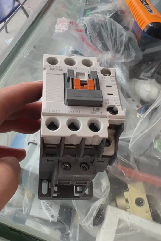
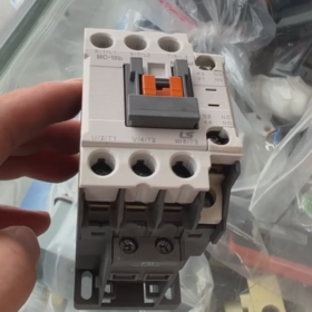
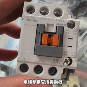
Basic Information: LS Electric’s MC series AC contactors come in a variety of specifications, such as MC-9b to MC-65a, among which the MC-10b is one type. It is applicable to 50Hz or 60Hz circuits and is mainly used for remotely connecting and disconnecting circuits, as well as controlling the start-up, stop and reversal of AC motors.
Product Features: This series of contactors offers a selection of AC and DC coils with various control voltage specifications; they feature a long service life and high reliability; their accessories are universal; they support rail or screw mounting for easy installation; and they are designed with anti-electric shock safety covers for safe operation.
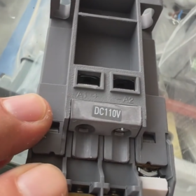
Technical Parameters: The rated insulation voltage ranges from 690V to 1000V. Under the AC-3 service category, when the rated operating voltage is 380V, different models correspond to different rated operating currents. Although the specific current parameter of the MC-10b is not clearly specified, the MC-9b of the same series has a rated operating current of approximately 9A under the AC-3 service category, which can be used as a reference. The allowable fluctuation range of its control voltage is 80%~110%Us, the operating ambient temperature ranges from -5℃ to +40℃, and the maximum applicable altitude is 2000 meters.
Application Fields: It is widely used in automatic control equipment, mechanical equipment, power control cabinets, etc. It can improve the operational efficiency of production lines and meet various industrial control requirements.
The common faults, root causes and professional troubleshooting methods of the South Korea LS MC-10b AC contactor (AC-3 category, suitable for motor control and other scenarios) are sorted out in a targeted manner based on its product characteristics (such as coil voltage allowable range of 80%~110%Us, rail/screw mounting, anti-electric shock design, etc.), and presented in a structured table for quick troubleshooting:
| Fault Phenomenon | Possible Causes | Troubleshooting Methods |
| 1. Coil fails to energize, contactor does not pull in | ① Control voltage does not reach the rated value (deviating from the range of 80%~110%Us); | ① Use a multimeter to measure the control voltage and ensure it complies with the product label (e.g., AC220V/DC24V), adjust the voltage to the allowable range; |
| ② Coil is burned out (measured coil resistance is infinite with a multimeter); | ② Replace the coil with the same model (genuine LS coil, voltage specification must match). If the coil burnout is accompanied by an unusual odor, check for short circuits in the control circuit; | |
| ③ Control circuit is open-circuited (loose wires, blown fuses, faulty push-button switches); | ③ Troubleshoot the control circuit wires, fuses and push-button switches, repair open-circuit points, and replace damaged components; | |
| ④ Coil terminals are loose or oxidized | ④ Tighten the terminals, polish the oxide layer with sandpaper, and apply conductive paste to enhance electrical contact | |
| 2. After coil energization, contactor pulls in unstably (jittering, abnormal noise) | ① Control voltage is too low (below 80%Us); | ① Measure the control voltage, check if the transformer load is overloaded, and increase the cross-sectional area of the control circuit wires if necessary; |
| ② Oil stains, rust or foreign objects on the end face of the coil iron core; | ② Disconnect the power supply, disassemble the contactor, clean the end face of the iron core with anhydrous ethanol to remove oil stains, rust and foreign objects, and ensure the iron core suction surface is flat; | |
| ③ Broken short-circuit ring of the iron core (unique to AC coils); | ③ Inspect the short-circuit ring (located in the groove on the end face of the iron core). If it is broken, replace the iron core or the entire contactor; | |
| ④ Loose installation (vibration caused by insecure rail or screw fixing) | ④ Re-tighten the rail buckles or mounting screws to ensure the contactor fits closely with the mounting surface and reduce vibration | |
| 3. Main contacts are ablated, blackened or have poor contact | ① Frequent switching of heavy loads or short-circuit currents (exceeding the breaking capacity of AC-3 category); | ① Inspect the load circuit to eliminate short-circuit faults. If frequent start-stop operations are required, select a contactor with higher breaking capacity (e.g., LS MC-12b); |
| ② Insufficient pressure of main contacts (spring aging); | ② Use a multimeter to measure the on-off resistance of the main contacts (should be close to 0Ω). If the resistance is too high, replace the contact assembly or the contactor; | |
| ③ Short circuit on the load side or motor locked-rotor; | ③ Check if the motor is locked-rotor, repair the motor bearings or mechanical jams, and install a thermal overload relay for protection; | |
| ④ Wear of contact material (number of switching operations reaches the service life limit) | ④ Record the number of switching operations, and replace the contactor in a timely manner when it reaches the product service life (usually more than 10⁵ times) | |
| 4. Main contacts are welded (cannot disconnect after pulling in) | ① Contact welding caused by short-circuit current; | ① Cut off the power supply immediately, forcibly disconnect the contacts with insulated tools, troubleshoot the causes of short circuits (e.g., motor winding short circuit, cable damage), and replace with a new contactor; |
| ② Insufficient contact pressure and long-term overload operation; | ② Inspect the contact springs. If aged, replace the springs or the contactor to avoid long-term overload; | |
| ③ Undersized contactor selection (rated current is lower than load current) | ③ Verify the load current. The rated current of MC-10b is approximately 10A (AC-3 380V). If the load current exceeds the rated value, replace it with a larger specification (e.g., LS MC-18b) | |
| 5. Auxiliary contacts have poor contact (control circuit failure) | ① Oxidation and ablation of auxiliary contacts; | ① Use the continuity test function of a multimeter to detect the auxiliary contacts. Lightly polish the oxide layer with fine sandpaper. If ablation is severe, replace the auxiliary contact module (accessories of LS MC series are universal); |
| ② Fatigue of contact springs; | ② Replace the fatigued springs or contact assembly; | |
| ③ Loose terminals of auxiliary contacts | ③ Tighten the terminals to ensure good crimping of wires | |
| 6. Contactor overheats (housing temperature exceeds the allowable value) | ① Load current exceeds the rated value (overload); | ① Install a thermal overload relay for protection to limit the overload duration. If long-term overload is unavoidable, upgrade the contactor specification; |
| ② Excessively high contact resistance of main contacts; | ② Clean or replace the main contacts to ensure good electrical contact; | |
| ③ Ambient temperature exceeds 40℃ (out of the operating range); | ③ Improve the installation environment (lower temperature, keep away from heat sources). If the ambient temperature cannot be adjusted, select a high-temperature resistant contactor; | |
| ④ Poor ventilation and excessive dust accumulation | ④ Regularly clean the dust on the contactor surface to ensure smooth ventilation | |
| 7. Mechanical jamming (unsmooth pull-in/disconnection) | ① Dust and oil contamination on the transmission mechanism; | ① Disconnect the power supply, disassemble the contactor, clean the transmission mechanism with anhydrous ethanol, and apply a small amount of lubricating grease (avoid excessive grease to prevent dust accumulation); |
| ② Deformation of the iron core or connecting rod; | ② Inspect the iron core and connecting rod. If deformed, replace the relevant parts or the contactor; | |
| ③ Installation angle deviation (exceeding the allowable range) | ③ Adjust the installation angle (horizontal installation is preferred), and ensure secure rail or screw mounting without tilting | |
| 8. Leakage current or small current conduction persists after disconnection | ① Reduced insulation caused by carbonization layer on the surface of main contacts; | ① Polish the carbonization layer on the main contacts with fine sandpaper. If insulation is severely degraded, replace the contactor; |
| ② Aging of internal insulation components of the contactor (e.g., housing, partition board); | ② Inspect the insulation components for damage or aging, and replace the damaged parts; | |
| ③ Parasitic current in the control circuit | ③ Install a bleeder resistor in the control circuit to eliminate the impact of parasitic current |
- Safety Precautions for Troubleshooting
- Before conducting any troubleshooting, disconnect the power supply of both the main circuit and the control circuit and wait for the capacitors to discharge completely (it is recommended not to touch the internal components within 10 minutes after power-off) to avoid the risk of electric shock or short circuit.
- When measuring the coil resistance, select the ohm range of a multimeter (2kΩ range is recommended). The coil resistance of LS MC-10b is usually several hundred to several thousand ohms (varies according to voltage specifications, e.g., approximately 1.5kΩ for AC220V coils and several tens of ohms for DC24V coils). An infinite resistance value indicates that the coil is burned out.
- When replacing contacts or coils, use genuine LS accessories to ensure model matching (e.g., coil voltage, contact current rating) to avoid secondary faults caused by incompatible accessories.
- Preventive Maintenance Recommendations (Extend Service Life)
- Regular Cleaning: Use compressed air to blow off dust on the surface and inside of the contactor every 3 to 6 months to prevent poor heat dissipation or mechanical jamming caused by dust accumulation.
- Contact Inspection: Measure the contact resistance of the main contacts every 12 months. Clean or replace the contacts if the resistance is greater than 50mΩ.
- Coil Maintenance: Regularly measure the control voltage to ensure it stays within the range of 80%~110%Us, preventing coil overheating due to voltage fluctuations.
- Installation Reinforcement: Check the mounting screws or rail buckles every 6 months to prevent loosening caused by vibration, which may affect contact performance.
- Load Matching: Ensure the load type (e.g., motor) complies with the AC-3 service category. Avoid using the contactor in heavy-duty scenarios such as AC-4 (inching, reversing). If such applications are required, select a dedicated contactor.
- Fault Scenarios That Cannot Be Resolved Independently
If any of the following situations occur, it is recommended to contact LS Electric’s technical support or professional maintenance personnel:
- The contactor housing is cracked or the iron core is severely deformed.
- The coil burns out repeatedly while the control voltage is normal and there is no short circuit in the control circuit.
- Main contacts are frequently welded and the fault cannot be resolved after eliminating load-related issues.
- Severe abnormalities such as unusual odor or smoke occur during the operation of the contactor.


")


NH42-63-318x560.png "CHINT PC-type automatic transfer switches (ATS)NH42-63/4SZ")

")

