 Contactor,circuit breaker,solar inverter,electric meter,solar batteries

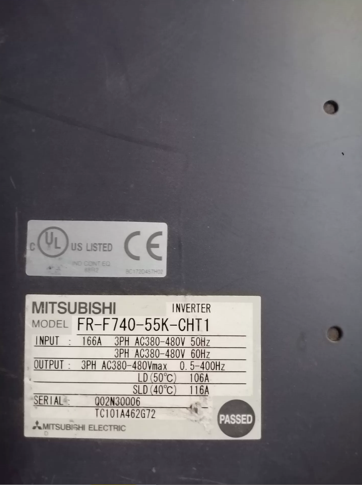


The FR-F740-S75K-CHT is a 3-phase 400V-class inverter from Mitsubishi Electric’s FREQROL‑F700 series, designed specifically for fan and pump applications. Optimized for 75kW quadratic torque loads, it is a classic flagship model for industrial energy-saving speed control and fluid control systems, compliant with Chinese CCC certification and domestic power grid standards.
- Model Explanation
| Code | Description |
| FR | General prefix for Mitsubishi FREQROL series inverters |
| F740 | F700 series, 3-phase 380~480V class, energy-saving model dedicated for fans and pumps |
| S75K | Applicable motor rating: 75kW three-phase induction motor; S indicates large-size heavy‑duty series |
| CHT | Version exclusive to Chinese market, adapted to local power grid, compliant with GB and CCC |
- Key Rated Electrical Specifications
| Item | Specification |
| Applicable motor capacity | 75kW (three-phase induction motor) |
| Rated output capacity | 110kVA for both SLD / LD duty |
| Rated output current | 144A (common for SLD light duty / LD heavy duty) |
| Overload capacity | SLD default: 110% rated current for 60s, 120% for 3s at 40°C |
| LD heavy duty: 120% rated current for 60s, 150% for 3s at 50°C | |
| Both feature inverse-time characteristics | |
| Input power specification | 3-phase AC 380~480V, 50/60Hz; allowable voltage fluctuation: 323~528V, frequency: ±5% |
| Output frequency range | 0.2~400Hz, speed control range 1:100 (under vector control) |
| Protection structure | Open type IP00, must be installed in a qualified enclosure |
| Cooling method | Forced air cooling |
| Approx. weight | 35kg |
| Dedicated DC reactor | FR-HEL-H75K |
- Core Functions & Features
- Dedicated Energy-Saving Control
Optimized for quadratic torque loads such as fans and pumps. Built-in optimal excitation control and energy-saving mode achieve up to 30% higher energy efficiency than conventional V/F control.
- Multi-Mode Precision Control
Supports V/F control, advanced magnetic flux vector control, general vector control. Stable low-speed torque. Suitable for constant-pressure water supply, multi-pump systems, closed-loop temperature/airflow control. Dual PID and sleep/wake functions included.
- High Reliability & Full Protection
Comprehensive protection: overcurrent, overvoltage, undervoltage, overheat, overload, stall prevention, ground fault. Adaptive to power fluctuations. Designed lifetime of main capacitors and fans exceeds 10 years.
- Rich Communication & Expansion
Standard RS485, Modbus-RTU. Optional CC-Link, Profibus-DP, DeviceNet cards for seamless integration into automation systems.
- User-Friendly Design
Standard FR-DU07 keypad: local start/stop, frequency setting, parameter tuning, fault monitoring. Parameters compatible with Mitsubishi inverter series.
- Main Applications
Primary: 75kW 3-phase 380V fans, pumps, compressors — industrial water supply/drainage, central AC water circulation, boiler ID/FD fans, HVAC, water treatment aeration/booster systems.
Secondary: Conveyors, mixers, ventilation equipment. Ideal for continuous operation requiring high efficiency, stability, and long service life.
- Installation & Commissioning Guidelines
- Installation: IP00 open type must be installed in a proper enclosure, vertically mounted with sufficient cooling space. Ambient temp: -10~+50°C. Avoid moisture, dust, corrosive gas, strong EMI.
- Wiring: Main input R/L1, S/L2, T/L3 → power supply; output U, V, W → motor. Never reverse input/output. Use suitable circuit breakers and contactors. Recommended DC reactor FR-HEL-H75K to improve power factor and reduce harmonics.
- Control Modes: PU (keypad), external terminal, communication. Perform motor auto-tuning first. Set acceleration/deceleration time, PID, and protection levels accordingly.
- Grounding: Reliable independent grounding, resistance ≤10Ω. Do not share ground with high-power equipment.
- Typical Faults & Troubleshooting
| Fault Code | Description | Main Checks |
| EOC1 | Overcurrent during acceleration | Check if acceleration time is too short, motor short鈥慶ircuit/ground fault, or load jam |
| EOV | Main circuit overvoltage | Check high input voltage, short deceleration time, or improper braking circuit |
| EUV | Main circuit undervoltage | Check phase loss, loose input terminals, or excessive power fluctuation |
| OH | Inverter overheat | Check fan failure, blocked air duct, or excessive ambient temperature |
| OL | Motor overload | Check motor stall, overload, or mismatched motor rated parameters |
Complete Guide to Braking Resistor Selection for Mitsubishi FR-F740-S75K-CHT
- Critical Pre-Selection Notes (Must Read)
The FR-F740-S75K-CHT is a 75kW 3-phase 400V fan/pump inverter with no built-in braking transistor or braking unit. It cannot directly connect external braking resistors.
An external braking unit must be installed first, then matched braking resistors. Otherwise, permanent damage to the inverter main circuit will occur.
1.1 Typical Applications Requiring Braking Resistors
Fast motor deceleration / stop, much shorter than free-run time
High-inertia loads (large fans, pumps, centrifuges)
Frequent `EOV` DC bus overvoltage faults during deceleration
Precise speed control without overshoot
Continuous braking for hoisting / lowering applications
1.2 Recommended Braking Unit
Use genuine Mitsubishi or compatible units:
| Item | Genuine Model | Key Parameters |
| Braking unit | FR-BU2-H75K | For 75kW 400V-class inverter, max withstand voltage 800V DC, IP00, forced air cooling |
| Minimum allowable external resistance | 6.5Ω | Never use resistance lower than this value, otherwise IGBT will burn out |
| Genuine matching resistor unit | MT-BR5-H75K | Standard resistance 6.5Ω, suitable for 10% ED duty, built‑in overheat protection |
- Braking Resistor Selection Rules
Core parameters: resistance, rated power, voltage class.
2.1 Resistance (R)
Must be ≥ 6.5Ω
Practical range: 6.5Ω ~ 20Ω
2.2 Rated Power (P)
Braking resistors are intermittent duty. Selection depends on ED% (duty ratio).
Genuine MT-BR5-H75K: 65kW, suitable for ED ≤10%.
2.3 Withstand Voltage & Type
Voltage class: ≥ 1000V DC
Preferred types:
- Corrugated stainless steel resistor — excellent heat dissipation, high overload
- Aluminum-housed resistor — compact, low duty
- Genuine MT-BR5 — plug-and-play, thermal protection
- Duty-Based Selection Table
| Duty Level | Typical Application | ED% | Recommended R | Recommended P | Notes |
| Light basic | Occasional stop, decel ≥30s, ≤10 starts per shift | ≤5% | 6.8Ω~10Ω | 7.5kW~10kW | Basic overvoltage protection only |
| General | Normal fan/pump, frequent starts, decel 10~30s | 5%~10% | 6.5Ω~7.5Ω | 10kW~15kW | Most common, cost‑effective |
| High‑frequency | High‑inertia fan/centrifuge, fast decel ≤10s | 10%~20% | 6.5Ω (standard) | 15kW~30kW | Enhanced cooling, parallel resistors |
| Continuous | Potential load, long‑term lowering | ≥20% | 6.5Ω (mandatory) | ≥30kW (genuine 65kW preferred) | Independent thermal protection + forced cooling |
3.1 Genuine Complete Set
Braking Unit: FR-BU2-H75K
Braking Resistor: MT-BR5-H75K (6.5Ω, 65kW)
3.2 Economic Compatible Types
Basic: RXLG 10kW 10Ω 1000V
General: RXLG 15kW 7.5Ω 1000V
Heavy: RXLG 30kW 6.8Ω 1000V (or two 15kW 13.6Ω in parallel)
- Wiring, Installation & Parameters
4.1 Safety Wiring Rules
Sequence: Inverter `P/+` → Braking Unit `P/+`; Inverter `N/-` → Braking Unit `N/-`; Braking Unit → Resistor.
Do NOT connect resistor directly to P/N.
Cable length ≤5m; max 10m for twisted pair.
Cable section ≥14mm², voltage rating ≥1000V.
Connect resistor thermal contact to inverter emergency stop.
4.2 Thermal Installation
Mount vertically, sufficient clearance, no enclosure blocking.
Keep ≥30cm from inverter and PLC.
For heavy duty: add forced cooling fan.
4.3 Key Inverter Parameters
| Parameter No. | Name | Setting | Description |
| Pr.30 | Regenerative brake selection | 1 | Enable external braking unit |
| Pr.70 | Special regenerative brake | 0 | For FR-BU2 series |
| Pr.8 / Pr.11 | Accel / Decel time | Set by load | Avoid overload and overvoltage trip |
| Pr.150 | Overvoltage stall level | 660V | Match braking unit voltage |
- Faults & Solutions
| Symptom | Main Checks |
| EOV overvoltage fault during deceleration | Loose resistor wire, faulty braking unit, excessive resistance, short decel time, incorrect parameters |
| Braking unit alarm / burnout | R < 6.5Ω, reversed wiring, resistor short, poor cooling |
| Resistor overheat / burnout | Under‑rated power, loose connection, IGBT breakdown, insufficient cooling |
| Weak braking, long stopping time | Excessive resistance, wrong parameters, braking unit disabled |


 General Purpose Power Relay")
 from Siemens SIRIUS series")

")

")

NH42-63-318x560.png "CHINT PC-type automatic transfer switches (ATS)NH42-63/4SZ")


