 Contactor,circuit breaker,solar inverter,electric meter,solar batteries


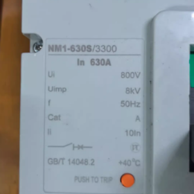
- Model Interpretation
| Model Segment | Description |
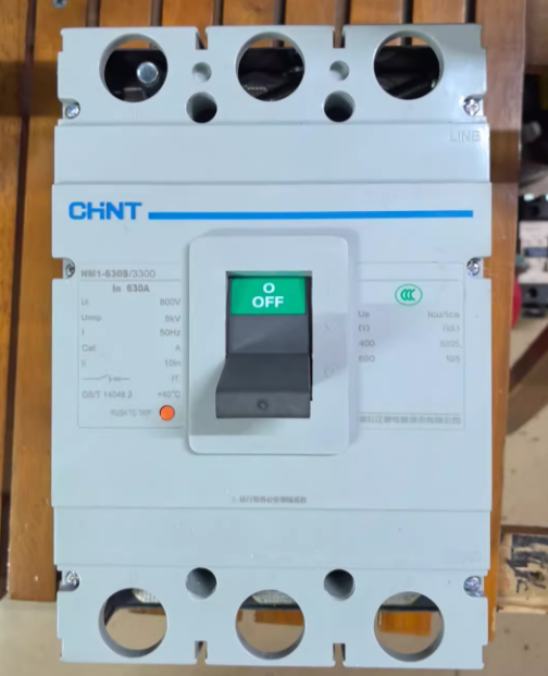
| NM1 | Product series code; CHINT Electric NM1 series molded case circuit breaker, suitable for power distribution protection and motor protection scenarios |
| 630 | Frame size rated current; the maximum current rating that this series of circuit breakers can carry is 630A |
| S | Breaking capacity class; Type S indicates standard breaking capacity, usually 35kA (refer to the product manual for details), suitable for conventional power distribution environments. Other classes in the same series include H (higher breaking capacity) and L (lower breaking capacity) |
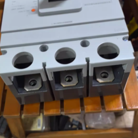
| 3300 | Pole number + trip unit type + accessory code |
| First two digits “33”: 3-pole circuit breaker, suitable for three-phase three-wire power distribution systems | |
| Last two digits “00”: no accessories (such as auxiliary contacts, undervoltage release, shunt release, etc.) | |
| 630A | Rated current; the rated operating current set for this circuit breaker is 630A |
- Core Technical Parameters
| Parameter Category | Specific Index |
| Rated Operating Voltage (Ue) | Three-phase AC 400V (50Hz), suitable for low-voltage power distribution systems |
| Rated Current (In) | 630A |
| Frame Current (Iu) | 630A |
| Breaking Capacity (Icu) | Class S: 35kA (at AC 400V) |
| Trip Unit Type | Thermal-magnetic trip unit (overload long-time delay protection + short-circuit instantaneous protection) |
| Overload Protection Characteristics | Long-time delay inverse-time characteristic; setting current Ir = 1.0In (630A). It can withstand 1.05In for long-term operation and will not trip within 1 hour under 1.3In |
| Short-Circuit Protection Characteristics | Instantaneous trip setting current Ii = 10In (6300A); it trips instantaneously when the short-circuit current reaches this value |
| Protection Class | IP20 (enclosure protection, preventing finger access) |
| Mounting Method | Fixed type/draw-out type (confirm specific model; fixed type is standard) |
| Wiring Method | Front-panel wiring (standard); rear-panel wiring is optional |
III. Functional Features
- Dual Protection Function: Integrates overload long-time delay protection and short-circuit instantaneous protection, which can effectively cut off overload and short-circuit fault currents to protect power distribution lines and equipment.
- Standard Breaking Capacity: The 35kA breaking capacity meets the short-circuit protection requirements of most industrial plants, commercial buildings, and civil power distribution scenarios.
- Modular Design: Supports the installation of accessories such as auxiliary contacts, shunt releases, and undervoltage releases to expand functions like remote control and fault signal feedback.
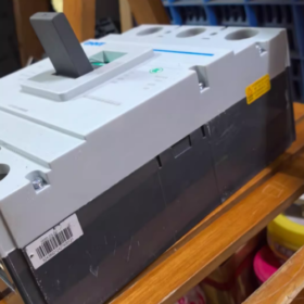
- Easy Operation: Adopts a manual energy storage operating mechanism with clear closing/opening actions, and is equipped with a transparent observation window for intuitive inspection of contact status.
- Long Electrical and Mechanical Service Life: Electrical service life ≥ 10,000 times; mechanical service life ≥ 20,000 times, suitable for power distribution scenarios with frequent switching.
- Application Scope
- Main Switch of Power Distribution System: Suitable for incoming line and bus section switches in 400V three-phase low-voltage power distribution systems, protecting the secondary side of transformers and outgoing circuits of power distribution cabinets.
- Industrial Equipment Protection: Can be used as the power-side protection switch for high-power motors (such as fans, water pumps, compressors with power ≤ 315kW).
- Building Power Distribution Scenarios: Protection of power distribution trunk lines in shopping malls, office buildings, factory workshops, etc., suitable for environments with conventional short-circuit current levels.
- Not Suitable For: Power distribution systems with high short-circuit current (> 35kA), precision equipment circuits requiring selective protection, and DC power distribution scenarios.
- Selection Suggestions
- Match Load Current: The rated load current should be ≤ 630A. If the load is a motor, the motor starting current must be considered (it is recommended that the instantaneous setting current of the trip unit be ≥ 8 times the rated motor current).
- Verify Breaking Capacity: The calculated on-site short-circuit current should be ≤ 35kA. If the short-circuit current exceeds 35kA, upgrade to the NM1-630H type (higher breaking capacity, usually 50kA/65kA).
- Accessory Selection:
For remote opening: Install a shunt release (code 3310).
For undervoltage protection: Install an undervoltage release (code 3320).
For fault signal feedback: Install auxiliary contacts (code 3308).
- Brand Replacement Reference:
| Brand | Replacement Model | Core Differences |
| Schneider | NSX630N 3P 630A | Higher breaking capacity (50kA) and higher price |
| Siemens | 3VL630 3P 630A | Richer modular accessories, suitable for Siemens power distribution systems |
| Delixi | CDM1-630S 3300 630A | Domestic brand of the same grade with consistent parameters and high cost performance |
- Troubleshooting
| Common Faults | Possible Causes | Solutions |
| Trips immediately after closing | 1. Short-circuit fault exists in the line | 1. Troubleshoot the short-circuit point of the line and close after repair |
| 2. Leakage on the load side (not applicable if no leakage accessory is installed) | 2. Check the insulation condition of the load | |
| 3. The instantaneous trip current setting is too small | 3. Confirm whether the trip unit setting current matches the load | |
| Does not trip during overload | 1. Thermal trip unit failure | 1. Replace the thermal trip unit |
| 2. The trip unit setting current is adjusted too high | 2. Re-adjust the setting current to the rated value | |
| 3. Circuit breaker contact adhesion | 3. Disassemble and inspect the contacts; replace the circuit breaker if necessary | |
| Cannot close | 1. Undervoltage release is not powered on (if installed) | 1. Check whether the power supply of the undervoltage release is normal |
| 2. Mechanical mechanism jamming | 2. Manually reset the mechanical mechanism and clean internal foreign objects | |
| 3. Line fault not eliminated | 3. Troubleshoot and eliminate line faults | |
| Abnormal heating during operation | 1. Loose wiring terminals | 1. Tighten the wiring terminals and apply conductive paste |
| 2. Load current exceeds the rated value | 2. Reduce the load or replace with a larger specification circuit breaker | |
| 3. Excessively high ambient temperature | 3. Improve ventilation and heat dissipation conditions |
VII. Installation and Maintenance Notes
- Before installation, confirm that the rated voltage and current of the circuit breaker match the on-site power distribution system, and check that the appearance is intact and the mechanism is free of jamming.
- Ensure that the terminals are tightened during wiring to avoid heating caused by poor contact. For front-panel wiring, the wire cross-section should match the 630A current (it is recommended to use 240mm² copper core cable).
- Regularly (every 6 months) inspect the contact status of the circuit breaker and the flexibility of the mechanical mechanism, and remove dust inside the enclosure.
- After a fault trip, the cause of the fault must be investigated first; do not close forcibly to avoid expanding the fault range.
Parameter Comparison Table of NM1-630S-3300 Series (400A/500A/630A)
| Parameter Category | Model Specification | ||
| Basic Parameters | NM1-630S-3300-400A | NM1-630S-3300-500A | NM1-630S-3300-630A |
| Frame Size Rated Current (Iu) | 630A | 630A | 630A |
| Rated Operating Current (In) | 400A | 500A | 630A |
| Rated Operating Voltage (Ue) | AC 400V 50Hz | AC 400V 50Hz | AC 400V 50Hz |
| Pole Number | 3-pole | 3-pole | 3-pole |
| Trip Unit Type | Thermal-magnetic (overload long-time delay + short-circuit instantaneous) | Thermal-magnetic (overload long-time delay + short-circuit instantaneous) | Thermal-magnetic (overload long-time delay + short-circuit instantaneous) |
| Protection Characteristics | |||
| Breaking Capacity (Icu, AC 400V) | 35kA | 35kA | 35kA |
| Overload Long-Time Delay Setting Current (Ir) | 400A (1.0In) | 500A (1.0In) | 630A (1.0In) |
| Overload Withstand Characteristics | Withstand 1.05In for long-term operation; no tripping within 1h under 1.3In | Withstand 1.05In for long-term operation; no tripping within 1h under 1.3In | Withstand 1.05In for long-term operation; no tripping within 1h under 1.3In |
| Short-Circuit Instantaneous Setting Current (Ii) | 10In = 4000A | 10In = 5000A | 10In = 6300A |
| Installation and Wiring | |||
| Protection Class | IP20 | IP20 | IP20 |
| Mounting Method | Fixed type/draw-out type (optional) | Fixed type/draw-out type (optional) | Fixed type/draw-out type (optional) |
| Recommended Matching Copper Core Cable Cross-Section | 185mm² | 240mm² | 240mm²/300mm² |
| Mechanical and Electrical Service Life | |||
| Mechanical Service Life | ≥20,000 times | ≥20,000 times | ≥20,000 times |
| Electrical Service Life | ≥10,000 times | ≥10,000 times | ≥10,000 times |
| Typical Application Scenarios | 1. Power-side protection for 185kW three-phase motors | 1. Power-side protection for 250kW three-phase motors | 1. Power-side protection for 315kW three-phase motors |
| 2. Power distribution branch switch (load current 350-400A) | 2. Power distribution trunk branch switch (load current 450-500A) | 2. Power distribution incoming line/bus section switch | |
| 3. Power distribution branch in small and medium-sized plants | 3. Power distribution branch in shopping malls and office buildings | 3. Power distribution trunk in large plants and high-rise buildings | |
Supplementary Selection Tips
- All specifications of this series have the same breaking capacity. Select the corresponding specification only according to the rated load current; there is no need to verify the breaking capacity additionally.
- If the load is a motor with frequent starting, it is recommended to select a specification with a rated current 1.1-1.2 times that of the motor to avoid overload false tripping.
- For the same frame size specification, the rated current can be adjusted by replacing the trip unit without replacing the circuit breaker body, reducing the later transformation cost.


")

NH42-63-318x560.png "CHINT PC-type automatic transfer switches (ATS)NH42-63/4SZ")


