
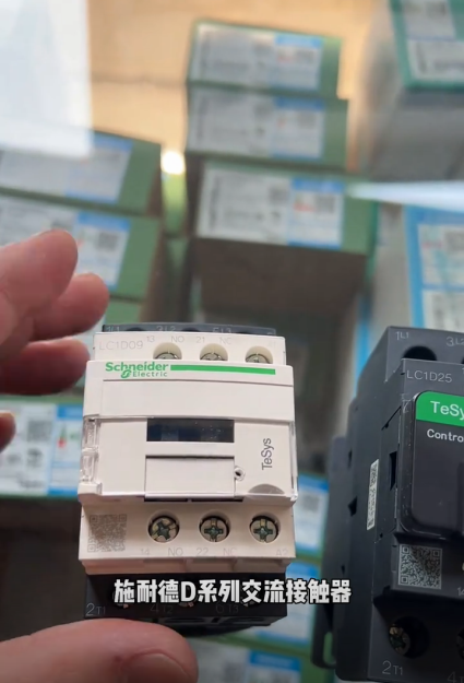
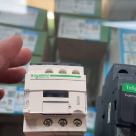
At a glance: The Schneider Electric LC1D25 is a TeSys D series 3-pole 25A AC contactor, suitable for AC-3 motor control (11kW/15HP at 400V). Standard width: 45mm. Supports DIN rail and screw mounting. Coil voltages available in multiple AC/DC ratings. Matching thermal overload relays: LRD16‑LRD32. Cross-brand replacements include ABB A16-30-10, Siemens 3RT6026-1AN20, etc.
- Part Number Interpretation
Base model: LC1D25
Full model format: LC1D25[Auxiliary Contacts][Coil Voltage][Frequency][Special Features]
| Code | Meaning | Example |
| LC1D | TeSys D series standard AC contactor | – |
| 25 | Rated operational current 25A (AC-3, 400V) | – |
| 2010/1/11 | Auxiliary contact configuration: 1NO/0NC, 0NO/1NC, 1NO/1NC | LC1D2510M7C (1NO) |
| M/Q/B/P | Coil voltage code: M=AC220V, Q=AC380V, B=AC24V, P=AC230V | LC1D2510M7C (AC220V) |
| 7月5日 | Frequency: 7=50/60Hz universal, 5=50Hz only | LC1D2510M7C (universal) |
| C/BL | Special features: C=standard, BL=low-power | LC1D2510M7C (standard) |
- Key Specifications
2.1 Main Circuit Parameters
| Parameter | Value | Notes |
| Poles | 3-pole (3NO) | Standard configuration |
| Rated operational current (AC‑3, 400V) | 25A | Typical for motor control |
| Rated operational current (AC‑1, 690V) | 40A | Resistive load |
| Rated operational voltage | ≤690V AC, ≤300V DC | Main circuit |
| Motor power (400V 3-phase) | 11kW (15HP) | AC-3 duty |
| Motor power (220V 3-phase) | 5.5kW (7.5HP) | AC-3 duty |
| Rated insulation voltage | 1000V | IEC standard |
| Rated impulse withstand voltage | 8kV | – |
2.2 Control Circuit Parameters
| Parameter | Value | Notes |
| Coil voltage range | AC24V~400V, DC24V~220V | Multiple options available |
| Coil power | Inrush: ≤9.5VA, Holding: ≤2VA | Standard version; lower for low-power type |
| Pick-up voltage | 85%~100% Un | – |
| Drop-out voltage | 20%~75% Un | – |
| Operating frequency | Up to 3600 operations/hour | AC-3 duty |
2.3 Mechanical & Mounting Parameters
| Parameter | Value | Notes |
| Dimensions | 45×85×92mm (without cover) / 45×85×101mm (with cover) | Common for LC1D25–LC1D38 |
| Mounting | 35mm DIN rail or screw mounting | Both compatible |
| Weight | Approx. 370g | Standard version |
| Protection degree | IP20 | Body only |
| Operating temperature | -5℃~+60℃ | Wide-temperature version available |
| Mechanical durability | ≥10 million operations | No-load |
| Electrical durability | ≥1 million operations | At rated AC-3 conditions |
- Selection Guide
3.1 Load Type Matching
AC-3 (motor control): Direct use for motors up to 25A, max. 11kW at 400V
AC-1 (resistive load): Up to 40A, suitable for heaters, lighting, etc.
DC load: Confirm DC rating; derating to ≤70% of AC rating recommended
3.2 Coil Voltage Selection
| Application | Recommended coil voltage | Advantage |
| Industrial automation | AC220V (M7) / AC380V (Q7) | Matches common factory voltages |
| Safety control circuits | AC24V (B7) / DC24V | Safety extra-low voltage |
| DC systems | DC24V~110V | Reduces electromagnetic interference |
3.3 Auxiliary Contact Extension
Standard: 1NO + 1NC built-in auxiliary contacts
Expansion: Add LAD series auxiliary modules; up to 4NO + 4NC
3.4 Protection Coordination
Overload protection: Use with LRD16‑LRD32 thermal overload relays (setting: 6.4~32A)
Short-circuit protection: Recommended C65N‑D/3P 32A or NSX series circuit breakers
Surge suppression: RC snubber for AC coils; freewheeling diode for DC coils
3.5 Mounting & Heat Dissipation
Mount vertically; keep ≥5mm above/below, ≥2mm left/right
Derate 10–15% for side-by-side installation
Above 40°C, derate approx. 1% per °C increase
- Cross-Brand Replacements
| Brand | Direct Replacement | Key Comparison |
| ABB | A16-30-10 (16A) / A26-30-10 (26A) | Same dimensions; A26 closer to 25A |
| Siemens | 3RT6026-1AN20 (25A) | Identical mounting, 1NO+1NC |
| Mitsubishi | S-T25 (25A) | Standard 3-pole, AC220V/380V coils |
| LS | GMC-22 (22A) / GMC-32 (32A) | Cost-effective; GMC-32 for heavy duty |
| Chint | NC1-2510 (25A) | Domestic alternative, cost advantage |
- Common Full Models & Applications
| Full Model | Description | Typical Application |
| LC1D2510M7C | 3P 25A, 1NO, AC220V coil, 50/60Hz | Water pumps, fans |
| LC1D2501Q7C | 3P 25A, 1NC, AC380V coil, 50/60Hz | Compressors, conveyors |
| LC1D2511B7C | 3P 25A, 1NO+1NC, AC24V coil | Safety circuits, E-stop |
| LC1D25BL | 3P 25A, low-power DC24V coil | Battery systems, energy-saving equipment |
Schneider Electric LC1D25 Contactor Mounting Dimensions Manual
At a glance: Standard dimensions: W45mm × H85mm × D92mm (without cover) / D101mm (with cover). Fits 35mm standard DIN rail. Screw mounting: 2×M4 slotted holes, horizontal center distance 35mm, vertical center distance 60–70mm adjustable.
- Basic Outline Dimensions (W×H×D)
| Configuration | Dimensions (mm) | Dimensions (in) | Notes |
| Without cover | 45 × 85 × 92 | 1.77 × 3.35 × 3.62 | Standard bare version |
| With cover | 45 × 85 × 101 | 1.77 × 3.35 × 3.98 | With safety cover |
| Low-power type | 45 × 85 × 99 | 1.77 × 3.35 × 3.90 | e.g., LC1D25BL |
Width 45mm: Common for LC1D25–LC1D38, compact mounting
Height 85mm: Base height without top auxiliary modules
Depth: Varies slightly by cover/coil; refer to actual unit
- Mounting Methods & Detailed Dimensions
2.1 DIN Rail Mounting (Recommended)
Fits 35mm standard DIN rail (EN 60715)
Locks onto center rear of contactor
Mount vertically (coil downward) for best cooling and stability
Clearance: ≥5mm top/bottom, ≥2mm left/right; derate 10–15% side-by-side
2.2 Screw Mounting
| Parameter | Value | Notes |
| Mounting holes | 2×M4 slotted holes | For M4×8 or M4×10 screws |
| Horizontal center distance | 35mm | Fixed |
| Vertical center distance | 60–70mm | Slotted for adjustment |
| Mounting plate thickness | 1.5–3mm | Galvanized steel or insulation plate |
| Tightening torque | 1.2–1.5N·m | Avoid damage |
- Add-On Module Dimensions
Top auxiliary modules (LAD series): W45mm, H≈20mm, depth unchanged
Side auxiliary modules: +≈18mm width per module, H and D unchanged
Thermal overload relays (LRD16‑LRD32): W45mm, H72.5mm, D79.9mm, direct snap-on
- Mounting Precautions
- Ambient temperature: -5℃~+60℃; derate above 40℃
- Avoid high vibration, heavy dust, corrosive gases
- Terminals: Main circuit (L1/L2/L3, T1/T2/T3) downward; coil (A1/A2) on right
- Leave gaps between adjacent contactors for ventilation


")


NH42-63-318x560.png "CHINT PC-type automatic transfer switches (ATS)NH42-63/4SZ")

")

