 Contactor,circuit breaker,solar inverter,electric meter,solar batteries


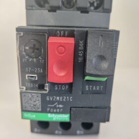
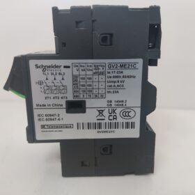
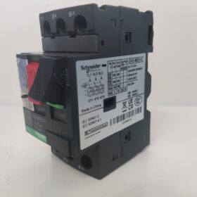
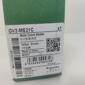
Schneider GV2-ME21C is a motor protection circuit breaker belonging to the TeSys GV2M series.
Basic Information
Brand: Schneider Electric
Series: GV2M Series
Product Type: Motor Protection Circuit Breaker
Technical Parameters
Rated Operating Voltage: 690V AC (compliant with IEC 60947-2), 600V AC (compliant with UL 508)
Thermal Overload Protection Setting Range: 17A to 23A
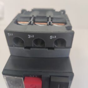
Pole Number: 3-pole
Electrical Service Life: 100,000 operations
Protection Class: IP20 (main unit, compliant with IEC 60529)
Dimensions: Height 89mm, Width 44.5mm, Depth 78.2mm
Product Weight: Approximately 0.26kg
Product Features
Versatile Functions: Equipped with short-circuit and overload protection functions; can be locked in the OFF position; auxiliary contacts can be used with signal switches or under tripping conditions.
Wide Operating Temperature Range: Reliable operation within the temperature range of -20°C to +60°C.
Comprehensive Certifications: Certified to multiple standards including IEC, UL, CSA, CCC and EAC; compliant with Green Premium standards (RoHS/REACh).
Application Fields: Suitable for scenarios requiring motor protection such as automatic control panels, MRI equipment, railway infrastructure and aerospace engineering.
Schneider GV2-ME21C is a DIN rail-mounted motor protection circuit breaker. Its installation must comply with electrical safety specifications and product manual requirements, which is divided into four core steps: pre-installation preparation, main unit installation, wiring operation and post-installation inspection, detailed as follows:
- Pre-installation Preparation
- Safety Confirmation
Disconnect all power supplies in the installation area and use a voltage tester to confirm the absence of voltage to prevent electric shock accidents.
Ensure that installers are equipped with electrical operation qualifications and wear protective equipment such as insulated gloves.
- Tool and Material Preparation
Tools: Phillips screwdriver (PH2 specification recommended), wire stripper, DIN rail cutting tool, torque screwdriver, voltage tester.
Materials: Suitable 35mm standard DIN rail (compliant with EN 60715), copper core wires (2.5-4mm², suitable for 17-23A current), insulating tape, wiring terminals (if extended wiring is required).
- Product Inspection
Inspect the appearance of the GV2-ME21C main unit for no cracks, deformation or missing parts; check that the handle switching between opening, closing and tripping positions is smooth without jamming.
Verify the parameters on the product nameplate (rated voltage 690V AC, setting current 17-23A) to ensure matching with the on-site motor and power supply parameters.
- Main Unit Installation (Two Methods, DIN Rail Installation Preferred)
Method 1: DIN Rail Installation (Mainstream Method)
- Fix the DIN rail: According to the installation location (inside the distribution cabinet/control cabinet), fix the 35mm DIN rail horizontally or vertically with screws, with the rail flatness error ≤ 0.5mm/m.
- Snap in the circuit breaker:
Hold the GV2-ME21C main unit and align the hook buckle on its top with the upper edge of the DIN rail.
Press down the bottom of the circuit breaker until a “click” sound is heard, confirm that the buckle is fully clamped to the rail, and ensure no looseness when shaking the main unit.
- Side-by-side installation of multiple units: When installing multiple GV2 circuit breakers side by side, reserve a gap of ≥ 5mm between adjacent products for heat dissipation and wiring operations.
Method 2: Screw Fixing Installation (No Rail Scenario)
- Positioning and drilling: Mark the drilling positions on the installation panel according to the mounting hole dimensions of the GV2-ME21C base (hole spacing approximately 45mm), with the drilling diameter matching M4 screws.
- Fixed installation: Pass M4 screws through the mounting holes of the circuit breaker base and tighten them on the panel, with the torque controlled at 1.5-2.0N·m to avoid damaging the base due to over-tightening.
- Wiring Operation (3-pole Wiring, Distinguish Between Incoming and Outgoing Lines)
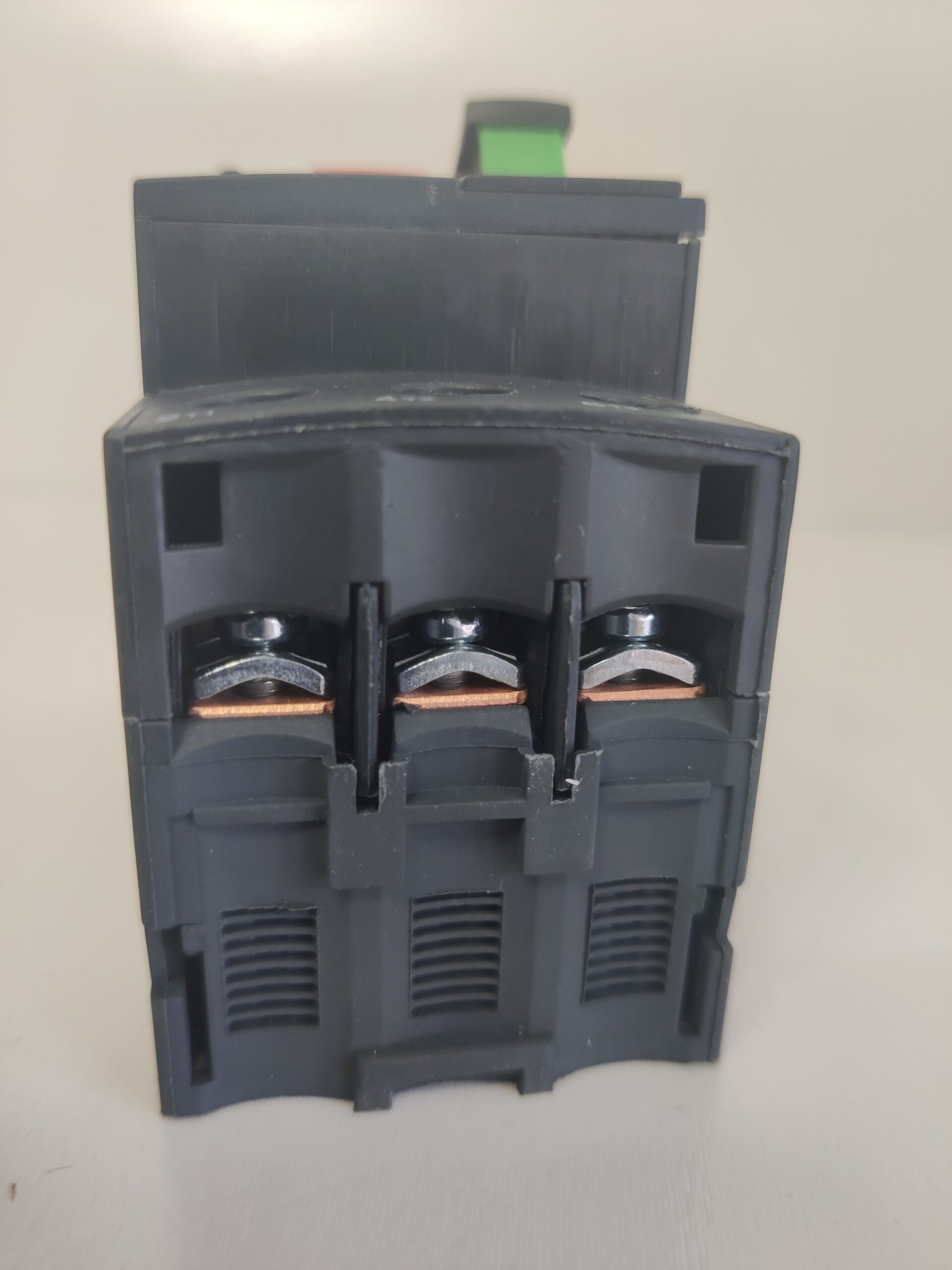
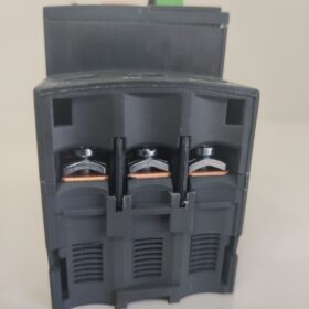
Terminal identification on the front of GV2-ME21C: L1, L2 and L3 are power incoming terminals, T1, T2 and T3 are motor outgoing terminals; reverse connection is strictly prohibited.
- Wire processing: Use a wire stripper to strip the insulation layer of the wire, with the stripping length of 8-10mm (matching the terminal jack depth), to avoid short circuits caused by excessively exposed conductors or poor contact caused by insufficient stripping length.
- Wiring tightening:
Insert the stripped copper core wire into the corresponding terminal jack and ensure that the wire is fully inserted to the bottom.
Tighten the terminal screw with a Phillips screwdriver, with the torque controlled at 1.5-2.5N·m; pull the wire lightly after tightening to confirm no looseness.
If multi-strand flexible wires are used, crimp cold-pressed terminals first before inserting into the jacks; direct insertion of flexible wires is prohibited.
- Auxiliary contact wiring (if extended functions are required):
GV2-ME21C can be equipped with auxiliary contact modules (such as GV2-AE11) for signal feedback or control circuits.
The auxiliary contact terminals are identified as 1NO (Normally Open) and 1NC (Normally Closed); connect them to the circuit according to control requirements and tighten the screws.
- Post-installation Inspection and Testing
- Mechanical Inspection
Operate the circuit breaker handle to ensure smooth switching between the three positions: OFF, ON and TEST without jamming.
Test the locking function: Toggle the handle to the OFF position, insert the locking device, and confirm that closing is not possible (to prevent misoperation).
- Electrical Testing
Pre-power-on inspection: Use a multimeter to measure the insulation resistance between incoming and outgoing terminals; the resistance value should be ≥ 1MΩ (to ensure no short circuit).
Protection function test: After power-on, press the TEST button on the handle; the circuit breaker should trip immediately. After reclosing, if the motor runs normally, it indicates that the overload protection function is effective.
- Protection Inspection
Confirm that the installation environment meets the requirements (temperature -20°C ~ +60°C, no humidity, corrosive gas or dust). The IP20 protection class requires preventing direct intrusion of water droplets and foreign objects.
Installation Notes
- Installation and wiring operations are strictly prohibited when the power is on.
- The rated current of the motor must be within the setting range of GV2-ME21C (17-23A), otherwise effective protection cannot be achieved.
- Installation and wiring must comply with local electrical specifications (such as GB 7251.1) and IEC 60947 standards.


")

NH42-63-318x560.png "CHINT PC-type automatic transfer switches (ATS)NH42-63/4SZ")


