
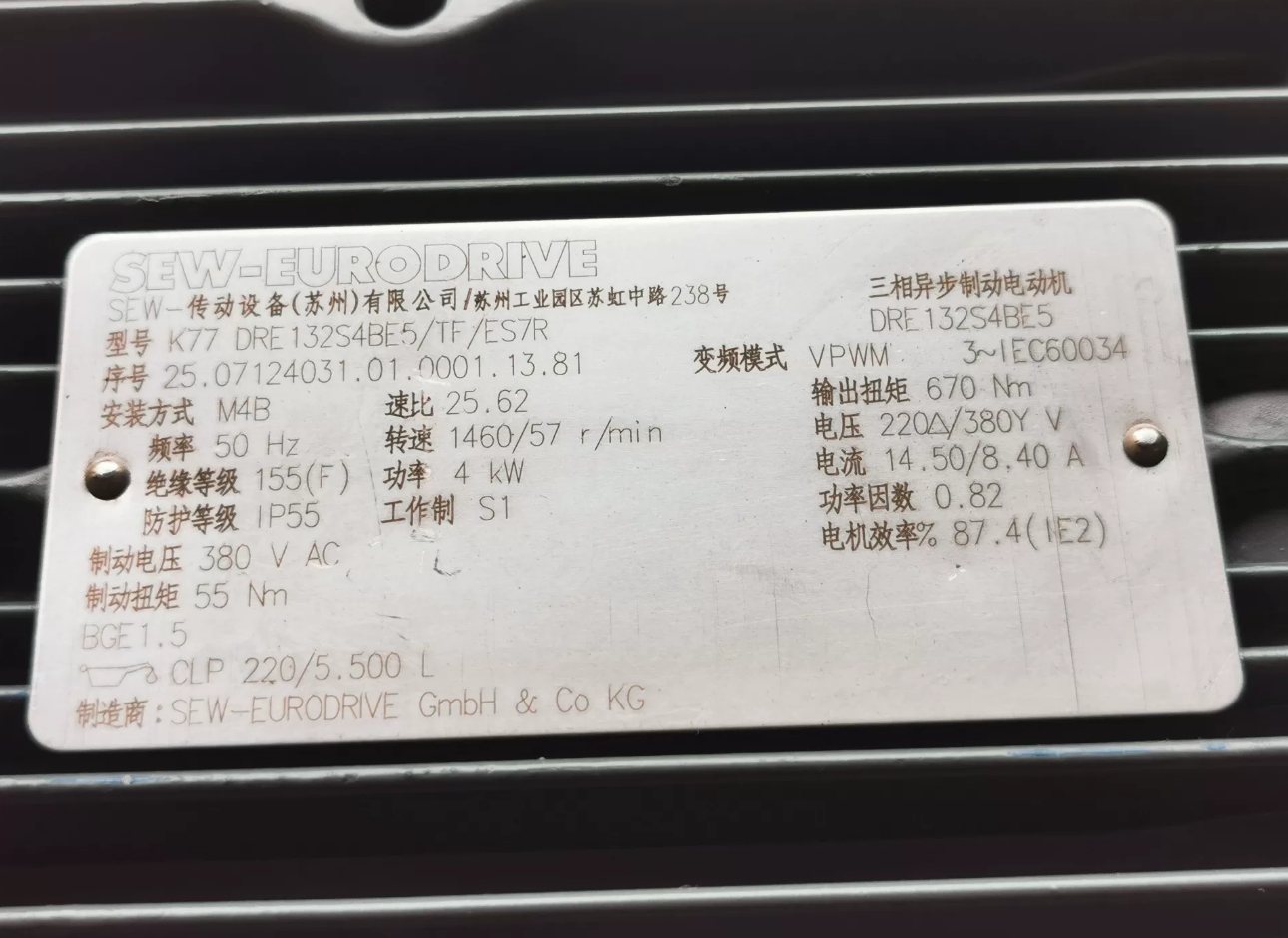

Model Code Breakdown
| Code Segment | Description | Details |
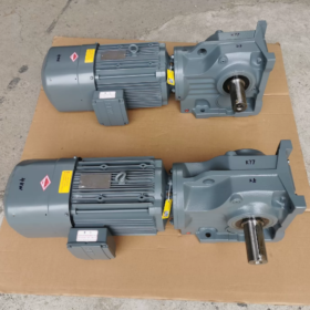
| K77 | Helical-bevel gear unit | K = Helical‑bevel (90° right‑angle drive), 77 = frame size, 3‑stage reduction, rated output torque approx. 600 Nm |
| DRE132S4 | Three‑phase asynchronous motor | DRE = Brake motor with integrated encoder, 132 = frame (c‑c height 132 mm), S = short frame, 4 = 4‑pole motor, rated speed approx. 1450 rpm, power 5.5 kW |
| BE5 | Brake specification | BE5 = SEW standard brake, dual‑coil design, DC 24 V supply, braking torque approx. 80 Nm, suitable for frequent start/stop applications |
| TF | Encoder type | TF = Incremental encoder, resolution typically 1024 ppr, used for speed feedback and positioning control, compatible with variable frequency drives |
| SEW | Brand logo | SEW‑EURODRIVE, leading German industrial drive manufacturer |
- Core Technical Parameters
2.1 Gear Unit Parameters
| Item | Value | Remarks |
| Construction | 3‑stage helical‑bevel | High efficiency, low noise, high‑rigidity cast‑iron housing |
| Ratio range | 5.36 ~ 188.72 | Standard ratios available; special ratios on request |
| Rated output torque | 600 Nm | S1 duty; service factor recommended: 1.2 ~ 1.5 |
| Max. output torque | 1200 Nm | Short‑time overload (S2 10 min) |
| Efficiency | 95% ~ 97% | Slightly decreases with increasing ratio |
| Mounting | Foot mounting (M1) / Flange mounting (M2) | Selectable per requirements |
| Output shaft | Solid / hollow shaft (Φ50 mm) | Keyed or shrink disk connection |
| Lubrication oil volume | Approx. 2.1 L | CLP 220 mineral oil, factory‑filled |
2.2 Motor Parameters
| Item | Value | Remarks |
| Rated power | 5.5 kW | S1 continuous duty |
| Rated voltage | 380/400 V 3‑phase | 50 Hz, star/delta connection |
| Rated current | 11.1 A | cosφ = 0.82, efficiency approx. 89% |
| Insulation class | Class F | Max. permissible temperature: 155 °C |
| Protection class | IP55 | Dust‑tight and splash‑proof, industrial environment |
| Cooling | IC411 | Self‑ventilated |
| Brake type | Spring‑set, electrically released | Fail‑safe brake for safety function |
| Encoder signal | A/B/Z three‑phase | Differential output, high noise immunity |
2.3 Complete Drive Unit Parameters
| Item | Value | Application Reference |
| Input speed | 1450 rpm | Motor rated speed |
| Output speed range | 7.68 ~ 270 rpm | Depends on selected ratio |
| Weight | Approx. 120 kg | Including motor and gear unit |
| Operating ambient temp. | -10C ~ +40C | Derate above 40C |
| Storage ambient temp. | -25C ~ +60C | Moisture protection required |
- Application Fields & Selection Guide
3.1 Typical Applications
Logistics & conveying: AS/RS stackers, conveyors, sorting systems
Packaging machinery: High‑speed packaging lines, printing equipment, labeling machines
Food & beverage: Filling machines, pasteurizers, labeling lines (food‑grade oil required)
Automotive manufacturing: Assembly lines, welding equipment, painting lines
Building materials: Tile production, glass processing, concrete batching plants
Paper & printing: Paper conveying, roll handling, printing machine drives
3.2 Key Selection Points
- Load analysis: Calculate actual working torque, ensure ≤ rated torque × service factor (1.2–1.5)
- Speed matching: Select ratio based on required output speed (i = motor speed / output speed)
- Duty matching: S1 for most applications; S2/S3 for frequent starts or shock loads
- Installation space: Confirm dimensions fit on‑site; K77 approx. 400×350×300 mm
- Control requirements: TF encoder supports closed‑loop control for precise positioning or synchronization
- Installation & Configuration Guide
4.1 Installation Procedure
- Foundation fixing: Secure with foundation bolts, level error ≤ 0.1 mm/m
- Motor connection: Ensure alignment between motor and gear unit; flexible coupling deviation ≤ 0.1 mm
- Brake wiring: BE5 brake requires separate DC 24 V supply; observe polarity
- Encoder wiring: Connect A/B/Z phases to inverter/controller; shield grounded at one end
- Lubrication check: Factory‑filled with CLP 220 oil; change after first 100 hours, then every 5000 hours
4.2 Electrical Configuration
| Component | Requirement | Notes |
| Inverter | Suitable for 5.5 kW motor, supports encoder feedback | Set brake parameters to match BE5 |
| Power supply | 380 V 3‑phase + DC 24 V control | Stability affects service life |
| Protection | Overload (1.15×In), short‑circuit, undervoltage | Surge protection recommended |
| Braking resistor | Optional, for frequent braking | Power ≥ 1 kW, resistance matched to inverter |
- Replacement Models & Selection Advice
5.1 SEW Alternative/Upgrade Models
| Model | Main Difference | Application |
| K77‑DRN132S4BE5‑TF | DRN = No integrated encoder interface, external only | Cost‑sensitive, low‑precision applications |
| K77‑DRS132S4BE5‑TF | DRS = No integrated brake | Continuous duty without fail‑safe braking |
| KA77‑DRE132S4BE5‑TF | KA = Torque arm mounting, output shrink disk available | Space‑limited, compact installation |
| K87‑DRE132S4BE5‑TF | K87 = Larger frame, rated torque 1000 Nm | Higher load, higher torque demand |
| K77‑DRE132M4BE5‑TF | 132M = Medium frame, 7.5 kW | Higher power requirements |
5.2 Cross‑Brand Equivalent Models
| Brand | Replacement Model | Match Level |
| Flender | KPB77BMP055L4 | ★★★★★ Full structural & parameter match |
| Bonfiglioli | 300L4 K77 5.5kW | ★★★★☆ Minor mounting differences |
| Siemens | SIMOGEAR GM132S‑5.5kW/K77 | ★★★★☆ Better control system compatibility |
| Domestic | KAF77‑Y5.5‑4P | ★★★★ Cost‑effective, some interchangeable parts |
- Maintenance & Troubleshooting
6.1 Regular Maintenance Schedule
| Interval | Item | Standard |
| Daily | Operating condition check | No abnormal noise/vibration, temp ≤ 80 °C |
| Monthly | Fastening check | Bolts torqued correctly, no loosening |
| Quarterly | Oil level check | Maintain at middle of sight glass |
| Every 1000 h | Brake inspection | Air gap 0.3–0.5 mm, smooth operation |
| Every 5000 h | Oil change | CLP 220 mineral or equivalent synthetic oil |
| Annually | Encoder check | Normal signal, secure, well protected |
6.2 Common Faults & Solutions
| Symptom | Possible Causes | Solution |
| Motor overheating | Overload, poor ventilation, power fault | Reduce load, clean fins, check power |
| Brake failure | Coil burnout, spring fatigue, excessive gap | Replace coil, adjust gap, check voltage |
| Encoder signal error | Loose wiring, poor shielding, encoder fault | Rewire, check grounding, replace encoder |
| Excessive gear unit noise | Worn gears/bearings, contaminated oil | Replace gears/bearings, change oil |
| Insufficient output torque | Wrong ratio, mismatched motor, mechanical jam | Reselect model, check mechanical system |
- Summary & Selection Recommendations
K77‑DRE132S4BE5‑TF is a well‑balanced 5.5 kW helical‑bevel gearmotor in the SEW K series, integrating a BE5 brake and TF encoder. It is ideal for industrial automation requiring precise positioning and frequent starts. Key advantages: high efficiency (>95%), high reliability, compact design, especially for space‑restricted installations.
Recommendations:
- For fluctuating loads, choose K87 series for higher torque reserve
- For ultra‑high precision, upgrade to BE11 brake and higher‑resolution encoder
- For food/pharma, use food‑grade lubricant and stainless fasteners
- For frequent braking, add an external braking resistor to extend service life
In‑Depth Maintenance Guide for SEW K77‑DRE132S4BE5‑TF
- Maintenance Overview & Schedule
This drive integrates a 5.5 kW brake motor + 3‑stage helical‑bevel gear unit + BE5 brake + TF encoder. Maintenance follows preventive first, corrective second:
| Level | Interval | Core Content | Personnel |
| Daily inspection | Daily/shift | Operation, temperature, noise, vibration, leakage | Operator |
| Monthly check | Monthly | Fasteners, oil level, brake function, encoder | Maintenance |
| Quarterly service | Quarterly | Cleaning, seals, brake air gap | Maintenance |
| Annual overhaul | Yearly / 3000 h | Full inspection, oil analysis, bearings | Specialist team |
| Major overhaul | 5 years / 15000 h | Disassembly, parts replacement, accuracy restore | SEW authorized service |
- Component Maintenance
2.1 Gear Unit (K77)
Lubrication (Most Critical)
First oil change: Mandatory after 100 hours to remove wear particles
Regular change: Every 5000 hours or 1 year (whichever comes first)
Oil type: CLP 220 mineral oil (standard); synthetic for < -10 °C; food‑grade for food industry
Oil level: Check 30 min after shutdown; level at middle of sight glass
Oil change procedure:
- Stop and cool to < 40 °C
- Open drain and breather plugs
- Drain completely
- Clean magnetic drain plug
- Refill to correct level
- Run 15 min and recheck level
Mechanical
Check foundation and flange bolts monthly (torque ~80–100 Nm)
Inspect shaft seals quarterly; replace if leaking
Vibration ≤ 2.8 mm/s; noise ≤ 85 dB(A)
Keep housing clean and ventilated
2.2 Motor (DRE132S4)
| Check | Interval | Standard | Action |
| Insulation resistance | 6 months | ≥ 1 MΩ (500 V megger) | Dry if low; increase frequency in humid areas |
| Bearings | Yearly | No noise, temp ≤ 80 °C | Regrease every 2000 h; fill 1/3–1/2 volume |
| Terminal box | Quarterly | Sealed, tight terminals | Torque terminals, clean, replace gaskets |
| Cooling | Monthly | Fan undamaged, vents clear | Clean fins, replace fan if broken |
| Insulation class | Continuous | Class F (155 °C) | Keep winding temp ≤ 120 °C |
2.3 BE5 Brake (Safety‑critical)
BE5: dual‑coil DC 24 V, torque ~80 Nm
Air gap: Check every 1000 h; target 0.3–0.5 mm, adjust 3 nuts evenly
Coil check: Resistance ~40–60 Ω; good insulation; secure wiring
Friction linings: Min thickness 2 mm; replace if worn
Manual release: Test monthly
Response: Brake ≤ 0.2 s; release ≤ 0.3 s
2.4 TF Encoder (Precision Component)
Check cable and grounding quarterly
Verify A/B/Z signals, 5 V ±0.2 V, resolution 1024 ppr
Protect from dust, oil, vibration
Route encoder cable separately from power cables
Recalibrate zero position after replacement
- Operating Monitoring & Fault Handling
3.1 Thresholds
| Parameter | Normal | Warning | Trip | Action |
| Housing temp | ≤ 80 °C | 85 °C | 90 °C | Check load, cooling, lubrication |
| Motor temp | ≤ 120 °C | 130 °C | 140 °C | Improve ventilation, reduce load |
| Vibration | ≤ 2.8 mm/s | 3.5 mm/s | 4.5 mm/s | Check coupling, bearings, foundation |
| Noise | ≤ 85 dB | 90 dB | 95 dB | Inspect gears, bearings, oil |
| Braking rate | ≤ 10/h | 15/h | 20/h | Add resistor, optimize control |
3.2 Fault Troubleshooting
| Symptom | Possible Causes | Priority | Solution |
| Brake failure | Coil, gap, power, jam | High | Check resistance, adjust gap, test DC 24 V |
| Encoder fault | Wiring, shielding, damage | High | Retighten, check ground, replace encoder |
| Oil leakage | Seal, overfill, blocked breather | Medium | Replace seal, adjust level, clean breather |
| Motor overheat | Overload, poor cooling, bad power | Medium | Reduce load, clean, check voltage |
| Abnormal noise | Gears, bearings, lubrication | Medium | Inspect mesh, bearings, oil quality |
- Long‑term Storage & Special Environments
4.1 Storage (>6 months)
Temp: -25 °C ~ +60 °C, humidity ≤ 85%, no corrosive gas
Rotate input shaft 3–5 turns monthly
Check oil and seals quarterly
Energize brake coil 10 min every 6 months
Protect encoder with moisture barrier
4.2 Special Conditions
| Condition | Adjustments |
| Frequent starts (>10/h) | Shorten oil change to 3000 h; check brake every 500 h; add resistor |
| Dusty environment | Dust cover; clean monthly; FKM seals; more frequent oil checks |
| Humid/corrosive | Stainless fasteners; anti‑corrosion coating; IP67 encoder; frequent insulation tests |
| High temp (>40 °C) | High‑temp synthetic oil; auxiliary fan; derate 10–15%; shorten intervals |
- Safety Rules (Mandatory)
- Lockout/tagout: Disconnect power before any work
- Discharge: Wait 15 min for inverter capacitors to discharge
- Brake safety: Secure load mechanically during brake service
- ESD protection: Use wrist strap for encoder/electronics
- Qualified personnel: Gear disassembly, brake adjustment, encoder setup only by trained staff
- Maintenance Records & Lifecycle Management
Keep records of:
Service date, operating hours
Replaced parts, serial numbers, reason
Oil analysis, vibration, temperature
Faults, root cause, remedies
Technician signature
Use data to predict failures and plan replacements.
- Summary & Key Warnings
The core of maintenance is lubrication, brake air gap, encoder signal integrity.
Following this guide ensures MTBF ≥ 15000 hours and service life over 10 years.
Key reminders:
First oil change at 100 hours is mandatory
BE5 brake gap directly affects safety
TF encoder shielding & grounding prevent interference
All work must be performed de‑energized


")


NH42-63-318x560.png "CHINT PC-type automatic transfer switches (ATS)NH42-63/4SZ")

")

