 Contator,disjuntor,inversor solar,medidor elétrico,baterias solares

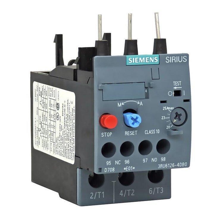


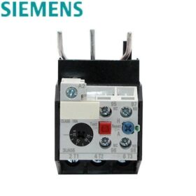
Detailed Explanation of Siemens 3UA50 Series Thermal Overload Relays (3.2-5A/4-6.3A/5-8A)
The Siemens 3UA50 series is a bimetallic relé de sobrecarga térmica, mainly used for overload protection and phase failure protection of AC motors, and also applicable for the overload protection of DC electromagnets and DC motors. Below is the detailed information of the three specific models you inquired about:
- Core Model and Parameter Comparison
| Modelo | Full Model | Faixa atual nominal | Classe de viagem | Insulation Voltage Ui | Suitable Contactors |
| 1F | 3UA5040-1F | 3.2-5 UM | Class 10A | 690V | 3TB40/41, 3TF30/31/40/41, etc.. |
| 1G | 3UA5000-1G | 4-6.3 UM | Class 10A | 690V | 3TD40/41, 3TE40, 3TW10/12/40/41, etc.. |
| 1H | 3UA5000-1H | 5-8 UM | Class 10A | 690V | 3TD40/41, 3TE40, 3TW10/12/40/41, etc.. |
- Key Technical Characteristics
(1) Funções de proteção
– Proteção contra sobrecarga: Achieved through the thermal effect of bimetallic strips; when the current exceeds the set value, the bimetallic strip bends to trigger the tripping mechanism.
– Phase Failure Protection: Adopts a differential phase failure protection design, which can reliably detect phase loss faults in three-phase circuits.
– Compensação de temperatura: Built-in temperature compensation device ensures stable protection characteristics within the ambient temperature range of -25℃ to +55℃.
(2) Operational Characteristics
– Trip Class 10A: Tripping time is 2s<tA≤10s at 7.2×Ie under cold condition; tripping time is ≤2min at 1.5×Ie under hot condition.
– Reset Modes: Supports two modes of automatic reset (sobre 5 minutos) and manual reset (manual pressing of the reset button required).
– Trip Indication: Equipped with a mechanical trip indicator to clearly display the operating status of the relay.
(3) Parâmetros Elétricos
– Overall rated operating current range of the 3UA50 series: 0.1~14.5 A
– Rated current of auxiliary circuit: 5A at AC-15/230V, 2.5A at AC-15/400V
– Grau de proteção: IP20 (limited protection against contact with live parts)
- Installation and Usage Key Points
(1) Métodos de instalação
– Combined Installation: Can be directly installed with mechanical interlocking to Siemens 3TB, 3TF, 3TD, 3TE, 3TW series contactors.
– Instalação independente: Special mounting accessory 3UX1418 (for 3UA50 series) é necessário.
– Mounting Dimension: Standard rail mounting, suitable for 35mm DIN rail.
(2) Setting Method
– Rotate the current adjustment knob on the top of the relay to align the pointer with the rated current value of the motor.
– The recommended setting current is 0.95~1.05 times the motor’s rated current.
(3) Notas
– Commissioning and maintenance must be performed by professional personnel.
– Avoid use in environments with severe vibration or corrosive gas.
– Ensure good heat dissipation when installed in combination with contactors to prevent affecting protection accuracy.
- Substitution and Compatibility Information
– Direct Substitution: BRAH Electric’s B3UA50 series can directly replace the Siemens 3UA50 series (por exemplo, B3UA50-00-1F replaces 3UA50-00-1F).
– Domestic Compatibility: Shenyang 213 JRS2-(3UA5.-) series thermal overload relays have the same technical parameters as the 3UA50 series and are interchangeable.
- Sugestões de seleção
- Select the appropriate current adjustment range according to the motor’s rated current, ensuring the motor’s rated current falls within the relay’s adjustment range.
- Confirm whether the auxiliary contact capacity meets the requirements according to the control circuit voltage.
- Select supporting accessories according to the installation method (combined installation/independent installation).
Guide for the Correct Matching Use of Thermal Overload Relays and Contactors
Relés de sobrecarga térmica (hereinafter referred to as “thermal relays”) and contactors are the core matching components of motor control circuits. Contactors are responsible for circuit on-off control and short-circuit protection in conjunction with fuses/circuit breakers, while thermal relays are dedicated to motor overload and phase failure protection. The two realize coordinated protection through mechanical interlocking + intertravamento elétrico, with the core matching principles of model adaptation, standard wiring, accurate setting and reliable interlocking. Below is a step-by-step practical guide including selection, installation, wiring, commissioning and troubleshooting, applicable to general industrial AC motor control scenarios (including the matching of the Siemens 3UA50 series thermal relays and 3TB/3TF series contactors you concerned about earlier).
- Basic Selection Matching: Core Parameter Matching (The Most Critical Premise)
Selection is the foundation of matching use, which should be carried out around the motor’s rated parameters and the compatibility of contactors/thermal relays to avoid protection failure or maloperation caused by parameter mismatch.
1.1 Core Current Parameter Matching
– Contator: Rated operating current Ie ≥ Motor rated current In (it is recommended to reserve a margin of 1.1~1.2 times to adapt to starting impact); for heavy-duty starting (por exemplo, fãs, bombas), the rated current of the contactor needs to be upgraded by one grade.
– Thermal relay: The current adjustment range must include the motor’s rated current In, and the set value is 0.95~1.05 times In; the rated heating current Ith of the thermal relay ≥ the rated operating current Ie of the contactor (to ensure the current-carrying capacity matching of the main circuit).
Exemplo: Siemens 3TB40 contactor (10A rated current) + 3UA5040-1F thermal relay (3.2-5UM) is suitable for three-phase asynchronous motors below 4kW with a rated current of 4~5A.
1.2 Installation Dimension and Series Compatibility
Contactors and thermal relays of the same brand are mostly exclusive series matching, with mechanical buckles that can be directly connected without additional accessories; for cross-brand matching, it is necessary to confirm the mounting hole spacing and rail compatibility (all are 35mm DIN standard rails) to avoid misalignment and poor contact after installation.
Common matching combinations:
– Siemens: 3TB/3TF contactors → 3UA50/51/52 series thermal relays
– Schneider: LC1D series contactors → LRD series thermal relays
– ABB: A series contactors → TA series thermal relays
– Marcas nacionais: CJX2 series contactors → JRS2 series thermal relays
1.3 Auxiliary Contact and Control Circuit Matching
– The capacity of the normally closed auxiliary contact of the thermal relay (1 group as standard, expandable for some models) must be ≥ the voltage/current of the control circuit (por exemplo, AC220V/5A) to ensure reliable disconnection of the contactor coil circuit.
– If there are indicator lights and alarm devices in the control circuit, thermal relays with normally open auxiliary contacts can be selected to realize overload alarm interlocking.
- Mechanical Installation Matching: Standard Installation to Ensure Heat Dissipation and Interlocking
The installation of contactors and thermal relays is divided into combined direct installation (recommended, small space occupation and reliable interlocking) and independent separate installation (suitable for scenarios with poor heat dissipation and large space), with the core requirements of firm and reliable fixation, good heat dissipation and non-jamming mechanical interlocking.
2.1 Recommended: Combined Direct Installation (Integrated Contactor + Thermal Relay)
- Align the top buckle of the thermal relay with the bottom slot of the contactor, push horizontally and buckle down to ensure no looseness (the installation is in place if there is no displacement when the thermal relay is shaken).
- Tighten the mounting end of the thermal relay with M4/M5 hexagon socket screws (for rail installation, clamp both the contactor and the thermal relay on the 35mm DIN rail at the same time), and control the tightening torque at 1.5~2N·m to avoid cracking the shell due to over-tightened screws.
- Post-installation inspection: The moving contact connecting rod of the contactor has no contact or jamming with the tripping mechanism of the thermal relay; the manual reset button and current adjustment knob of the thermal relay are exposed for easy operation.
2.2 Alternative: Independent Separate Installation (Separate Rail Mounting)
- Clamp the contactor and thermal relay on the 35mm DIN rail separately with a spacing of ≥20mm to avoid mutual heat conduction during operation (the thermal relay is a temperature-sensitive component, and the protection accuracy will decrease by about 10% for every 10℃ increase in ambient temperature).
- The main circuit wiring shall be connected with hard wires or copper bars to reduce line resistance and avoid the influence of terminal heating on the thermal relay’s judgment.
2.3 General Installation Notes
– Installation direction: Vertical installation (in line with the designed heat dissipation direction of the component); horizontal/inverted installation is prohibited, otherwise it will cause the deviation of the thermal relay’s tripping characteristics.
– Requisitos ambientais: Keep away from areas with high temperature, oil pollution and severe vibration, and the protection grade shall be adapted to the on-site conditions (por exemplo, add a protective cover in dusty environments, IP20→IP54).
– Avoid blocking: The heat dissipation holes of the thermal relay and the air vents of the contactor’s arc extinguishing chamber shall not be blocked to ensure timely heat dissipation.
- Electrical Wiring Matching: Circuit-by-Circuit Wiring to Ensure Effective Interlocking and Protection
Electrical wiring is divided into the main circuit (power circuit, high current) and the control circuit (low current, interlocking and control), with the core principles of corresponding phase sequence, firm wiring and correct interlocking. It is strictly forbidden to reverse the main circuit and the control circuit or have loose wiring terminals.
3.1 Fiação do Circuito Principal (Three-phase L1/L2/L3, Contactor → Thermal Relay → Motor)
- Connect the power incoming lines (L1, L2, L3) to the upper end of the contactor’s main contacts, and the lower end of the contactor’s main contacts to the upper end of the thermal relay’s main wiring terminals in a one-to-one phase sequence correspondence (L1→L1, L2→L2, L3→L3) to avoid phase failure protection failure.
- Connect the lower end of the thermal relay’s main wiring terminals to the motor stator winding; for single-phase motors or two-speed motors, connect them in phases according to the motor wiring diagram.
- Especificações de fiação: Use copper wires matching the terminal aperture, with moderate wire stripping length (avoid exposed core wires); crimp wire lugs (crimping is mandatory for wires ≥10mm²); tighten the terminal screws (torque 2~3N·m); pull the wires slightly after wiring to ensure no looseness.
- Aterramento: The metal shells of the thermal relay and contactor shall be reliably grounded with yellow-green double-color wires (grounding resistance ≤4Ω) para evitar vazamento elétrico.
3.2 Fiação do Circuito de Controle (Essencial: Normally Closed Contact of Thermal Relay in Series with Contactor Coil Circuit)
The core interlocking logic of the control circuit: After the thermal relay trips due to overload, the normally closed contact is disconnected → the contactor coil loses power → the main contacts are disconnected → the motor is powered off for protection.
General wiring steps (taking AC220V control circuit as an example, button start-stop mode):
- Connect the live wire L to the normally closed contact of the stop button → connect to the normally open contact of the start button → connect in parallel with the normally open auxiliary contact of the contactor (for self-holding).
- Connect the normally closed auxiliary contact of the thermal relay in series after the self-holding circuit → connect to one end of the contactor coil.
- Connect the other end of the contactor coil to the neutral wire N (for AC380V control circuit, connect to another phase live wire L2/L3).
- Opcional: Connect the normally open auxiliary contact of the thermal relay in series with the alarm indicator light/buzzer and access the control circuit to realize overload alarm.
Critical Prohibition: The normally closed contact of the thermal relay is strictly forbidden to be connected in parallel with the contactor coil circuit, otherwise the overload interlocking protection function will be lost; the control circuit wires shall be copper wires ≥1.5mm² to avoid heating and disconnection of thin wires.
3.3 Wiring Inspection Key Points
– Phase sequence: The L1/L2/L3 phase sequence of the main circuit is corresponding without wrong connection or missing connection.
– Interlocking: Press the manual trip test button of the thermal relay by hand, the normally closed contact of the thermal relay should be disconnected; at this time, when the control circuit is connected, the contactor should not be able to pull in.
– Insulation: After wiring is completed, measure the insulation resistance between the main circuit and the ground, and between phases with a 500V megohmmeter; ≥0.5MΩ is qualified, and the insulation resistance of the control circuit ≥1MΩ is qualified.
- Setting and Commissioning: Accurate Setting to Verify Protection Functions
After wiring is completed, it is necessary to set the current of the thermal relay and simulate overload/phase failure faults to verify the coordinated protection effect of the contactor and the thermal relay to ensure no maloperation or protection failure.
4.1 Thermal Relay Current Setting
Rotate the current adjustment knob on the top of the thermal relay to align the pointer with the motor rated current In (if the actual operating current of the motor is slightly lower, it can be set to 0.95In to avoid light-load tripping); tighten the knob lock nut (se houver) after setting to prevent the set value from deviating due to vibration.
4.2 Reset Mode Selection
The thermal relay has two reset modes: manual reset and automatic reset, which are switched by the reset lever on the side:
– Manual reset is recommended for industrial sites: After overload tripping, manual fault investigation (por exemplo, motor locked rotor, line short circuit) é necessário, and power supply can only be restored after pressing the reset button to avoid restarting the motor when the fault is not eliminated.
– Automatic reset is only applicable to simple light-load and unattended scenarios, with a reset time of about 5~10 minutes (the normally closed contact is automatically closed after the thermal relay is cooled).
4.3 Interlocking Protection Function Test
(1) Overload Protection Test
- Turn on the power, press the start button, the contactor pulls in, and the motor runs normally.
- Increase the motor operating current to 1.2 times the set current with a voltage regulator or load box, observe the tripping time of the thermal relay (Class 10A thermal relay trips within about 20 minutos); after tripping, the contactor should lose power and disconnect immediately, and the motor stops running.
- Reset the thermal relay after cooling, press the start button, the contactor should pull in normally and the motor resumes running.
(2) Phase Failure Protection Test
- Disconnect one phase of the main circuit (por exemplo, L1) when the motor is running normally to simulate a phase failure fault.
- Observe that the thermal relay should trip quickly within a few minutes (with differential phase failure protection design, the three-phase current is unbalanced after phase loss, and the bimetallic strip bends rapidly), and the contactor loses power and disconnects to realize phase failure protection.
(3) Interlocking Reliability Test
Press the manual trip test button (vermelho, black for some models) of the thermal relay, the thermal relay should trip immediately, the normally closed contact is disconnected, and the contactor releases due to power loss; after resetting the test button, the contactor can pull in normally without jamming.
- Daily Use and Maintenance: Extend Service Life and Ensure Protection Accuracy
- Regular inspection: Check the wiring terminals for heating and looseness every month (measure the terminal temperature with an infrared thermometer, ≤60℃ é normal); check that the shells of the thermal relay and contactor are free of cracks and deformation, and the auxiliary contacts are free of ablation.
- Cleaning and dust removal: Clean the dust and oil in the heat dissipation holes of the thermal relay and the arc extinguishing chamber of the contactor with compressed air every quarter to avoid affecting heat dissipation and arc extinguishing.
- Reset inspection: After each overload tripping, check whether the bimetallic strip of the thermal relay is deformed or jammed; replace it immediately if damaged, and it is forbidden to reset by force.
- Replacement principle: When the thermal relay or contactor has faults such as terminal ablation, coil burnout and contact welding, it must be replaced with the same model to avoid parameter mismatch caused by cross-model matching.
- Troubleshooting of Common Matching Faults (High-Frequency Problems)
| Fenômeno de falha | Core Causes | Soluções |
| The thermal relay trips immediately after the motor starts | 1. Excessively small setting current of the thermal relay; 2. Wrong phase sequence/missing phase in the main circuit; 3. Motor locked rotor/overload | 1. Reset the thermal relay current to the motor’s rated current; 2. Check the phase sequence of the main circuit and repair the phase loss point; 3. Investigate the motor load and eliminate the locked rotor |
| The thermal relay does not trip when the motor runs overloaded | 1. Excessively large setting current of the thermal relay; 2. Loose wiring terminals of the thermal relay with no heat conduction; 3. Failure of the bimetallic strip | 1. Reduce the thermal relay setting current to 0.95~1.05In; 2. Tighten the wiring terminals and re-crimp the wire lugs; 3. Replace the thermal relay |
| The contactor disconnects immediately after pulling in | 1. Poor contact of the normally closed contact of the thermal relay; 2. Loose wiring of the control circuit; 3. Maloperation of the thermal relay | 1. Clean/replace the auxiliary contact of the thermal relay; 2. Check the control circuit wiring and tighten the terminals; 3. Check whether the thermal relay is affected by vibration/high temperature |
| The thermal relay does not act in case of phase failure | 1. The main circuit phase sequence is not connected in correspondence; 2. The thermal relay has no phase failure protection function; 3. Light-load operation of the motor | 1. Rewire according to L1→L1, L2→L2, L3→L3; 2. Replace with a thermal relay with differential phase failure protection; 3. Add a phase failure protector for light-load scenarios |
| The contactor coil is frequently burned out | 1. Insufficient capacity of the thermal relay’s auxiliary contact; 2. Unstable voltage of the control circuit; 3. Undersized contactor selection | 1. Replace with a large-capacity auxiliary contact or add an intermediate relay; 2. Install a voltage stabilizer; 3. Upgrade the rated current grade of the contactor |
- Notas básicas de segurança
- Toda a instalação, wiring and commissioning operations must be carried out with the power supply completely disconnected; pendure um “Sem ligar” sinal de alerta para evitar choque elétrico.
- Thermal relays are only suitable for overload protection and are strictly forbidden to replace fuses/circuit breakers for short-circuit protection; the main circuit must be connected in series with fuses (RT18 series) or molded case circuit breakers (MCCB) to realize graded protection for short circuit and overload.
- For large-capacity motors (≥75kW) and motors with soft start/frequency conversion start, electronic thermal overload relays or motor protectors shall be selected to avoid maloperation of traditional bimetallic thermal relays caused by starting impact.
- For special environments such as explosion protection, corrosion protection and high altitude, special explosion-proof/corrosion-resistant contactors and thermal relays shall be selected to adapt to on-site environmental requirements.
Cross-Brand Direct Substitution Model Comparison Table for Siemens 3UA50 Series Thermal Overload Relays
Below are the corresponding Schneider, ABB, BRAH Electric and domestic compatible models for the 3UA50 40-1F (3.2-5UM), 1G (4-6.3UM) and 1H (5-8UM) you concerned about. All are direct substitution schemes with the same current range, the same trip class (Class 10A) and matching installation and electrical characteristics, suitable for the original 3TB/3TF and other series contactors.
| Siemens Model | Corrente nominal | Schneider | ABB | BRAH Electric | Domestic Compatibility (Tengen/Delixi/Chint) | Suitable Contactor Series |
| 3UA5040-1F | 3.2-5 UM | LRD08C (3.2-5UM) | TA25DU05 (3.2-5UM) | B3UA50-00-1F | JRS2-12.5/Z (3.2-5UM) | 3TB40/41, 3TF30/31/40/41, etc.. |
| 3UA5000-1G | 4-6.3 UM | LRD10C (4-6.3UM) | TA25DU06 (4-6.3UM) | B3UA50-00-1G | JRS2-12.5/Z (4-6.3UM) | 3TD40/41, 3TE40, 3TW10/12/40/41, etc.. |
| 3UA5000-1H | 5-8 UM | LRD12C (5-8UM) | TA25DU08 (5-8UM) | B3UA50-00-1H | JRS2-12.5/Z (5-8UM) | 3TD40/41, 3TE40, 3TW10/12/40/41, etc.. |
Key Substitution Instructions
- Parameter Consistency: All substitution models are of Class 10A trip class with a rated insulation voltage ≥690V, and the current-carrying capacity of the main circuit matches the original 3UA50 series to ensure consistent overload and phase failure protection performance.
- Compatibilidade de instalação
Contactors and thermal relays of the same brand can be directly installed with mechanical interlocking; for cross-brand combination, if it is 35mm DIN rail installation, it is necessary to confirm the rail buckle compatibility, and special mounting accessories are required for some models.
The domestic JRS2 series has the same installation dimensions as the 3UA50 series and can be directly replaced with plug-in installation.
- Wiring and Auxiliary Contacts: The capacity of the normally closed auxiliary contacts of the substitution models is all ≥AC-15/230V 5A, which can be directly connected in series with the original contactor coil circuit to realize overload interlocking protection; for alarm functions, models with normally open contacts can be selected.
- Notas
After substitution, the current must be reset to 0.95-1.05 times the motor’s rated current to ensure protection accuracy.
If the original system is a Siemens special mechanical interlocking combination, it is recommended to test the installation and interlocking reliability first during cross-brand substitution to avoid mechanical jamming.


")


")

NH42-63-318x560.png "Chaves de transferência automática tipo PC CHINT (ATS)NH42-63/4SZ")


