

Prezentare generală a produsului
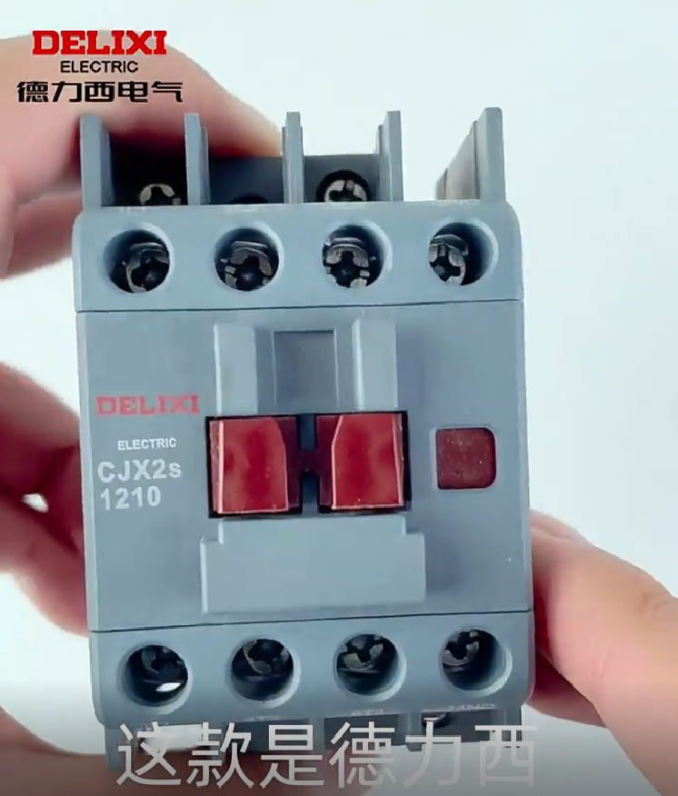
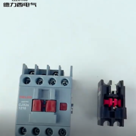
Delixi CJX2s-1210 este un 3-contactor AC poli aparținând seriei Navigator, special conceput pentru controlul și protecția motorului. Adoptarea unei platforme tehnologice de nouă generație, este potrivit pentru scenarii de operare frecventă în regim AC-3 (curent nominal de operare de 12A la tensiune sub 400V), cu fiabilitate ridicată, durată lungă de viață și instalare ușoară.
Explicația modelului: CJX2s (cod de serie) 12 (curent nominal de funcționare 12A) 10 (1 contact auxiliar normal deschis, 0 contacte auxiliare normal închise)
Aplicația de bază: Este folosit pentru pornire, controlul opririi și inversării motoarelor asincrone trifazate în sistemele de control al automatizărilor industriale. Poate fi combinat cu releele termice de suprasarcină din seria JRS1Dsp pentru a realiza protecția împotriva suprasarcinii motorului și a defecțiunii de fază.
- Parametrii tehnici de bază (Specificatii tehnice)
| Categoria parametrilor | Specificații detaliate | Observații |
| Parametrii de bază | ||
| Numărul de pol | 3 stâlpi | Tensiunea nominală a circuitului principal de până la 690 V |
| Curent nominal de operare (Ie) | 12O (AC-3, 400V) | Curent de încălzire convențional (Ea): 25O |
| Tensiune nominală de operare (Ue) | 400V/690V | Respectă GB 14048.4 standard |
| Configurarea contactelor auxiliare | 1NU (1 Deschis normal) | Fără contacte încorporate normal închise, expansiune externă disponibilă |
| Parametrii bobinei | ||
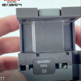
| Tensiune nominală de control (Uc) | AC 220V/380V/24V/36V/110V/240V | Universal pentru 50/60Hz, Bobina DC personalizabila |
| Gama de tensiune de preluare | 70%-120% Uc | Se adaptează la fluctuațiile tensiunii rețelei pentru o funcționare mai stabilă |
| Interval de tensiune de întrerupere | 20%-75% Uc | Asigură o rupere sigură |
| Consumul de energie al bobinei | Ridicare: aproximativ. 70VA; Deţinere: aproximativ. 7VA | Design de economisire a energiei pentru a reduce creșterea temperaturii de funcționare |
| Parametri de performanță | ||
| Tensiune nominală de izolație (Ui) | 800V | Distanța liberă și de curgere îndeplinesc cerințele de izolație |
| Tensiune nominală de rezistență la impuls (Ump) | 8kV | Rezistență puternică la supratensiune |
| Durată de viață mecanică | ≥ 10 milioane de operațiuni | Tehnologie de contact argintie îmbunătățită pentru o rezistență excelentă la arc |
| Durată de viață electrică (AC-3, 400V, 12O) | ≥ 1 milioane de operațiuni | 60% durată de viață mai mare decât media industriei pentru operațiuni frecvente |
| Frecvența nominală de operare | 1200 operațiuni/oră | Potrivit pentru scenarii frecvente de control pornire-oprire |
| Datoria | AC-3 (pornirea motorului cu colivie) | Poate fi folosit pentru AC-1 (sarcină rezistivă) și AC-4 (inversarea motorului) cu derating |
| Parametrii de mediu | ||
| Temperatura de operare | -25℃ ~ +55℃ | Altitudine ≤ 2000m, umiditate ≤ 95% (fara condens) |
| Clasa de protectie | IP20 | Previne contactul degetelor cu piesele sub tensiune; trebuie instalat în interiorul dulapurilor electrice |
| Parametrii de instalare | ||
| Metoda de montare | Montare standard pe șină DIN de 35 mm / fixare cu șuruburi | Distanța minimă între contactori ≥ 50 mm pentru disiparea căldurii |
| Dimensiuni generale | Aproximativ. 50mm × 80 mm × 58 mm | Greutate: aproximativ. 320g |
| Blocuri terminale | Circuitul principal: Șuruburi M4; Circuit auxiliar: Șuruburi M3 | Secțiunea transversală a firului circuitului principal: 1.5-4mm²; Secțiunea transversală a firului circuitului auxiliar: 0.5-1.5mm² |
- Caracteristici structurale și avantaje
3.1 Inovații structurale de bază
Sistem de contact din aliaj de argint: Contactele principale adoptă materiale din aliaj de argint de dimensiuni mari, care sunt rezistente la eroziunea arcului, reduce rezistența de contact, reduce creșterea temperaturii și prelungește durata de viață.
Sistem optimizat de stingere a arcului: Barierele de contact principale extinse măresc distanța de curgere și îmbunătățesc rezistența izolației. Opțional este disponibil un capac transparent pentru mediile cu praf.
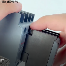
Design modular: Contacte auxiliare, bobinele și capacele de stingere a arcului sunt componente independente, facilitând întreținerea și înlocuirea, iar numărul de contacte auxiliare poate fi extins în mod flexibil.
3.2 Avantaje de performanță
Adaptabilitate largă la tensiune: Gama de tensiune de preluare a bobinei de 70%-120% Uc îl face potrivit pentru site-uri industriale cu tensiune instabilă.
Design cu consum redus de energie: Consumul de putere de menținere este doar 1/10 a consumului de putere de preluare, obținerea unui efect semnificativ de economisire a energiei și reducerea costurilor de operare.
Compatibilitate perfecta: Se potrivește perfect cu releele termice de suprasarcină din seria JRS1Dsp cu dimensiuni de instalare potrivite, formând o unitate completă de protecție a motorului.
- Ghid de selecție și scenarii de aplicare
4.1 Scenarii tipice de aplicare
Controlul direct de pornire și oprire a motoarelor asincrone trifazate (≤ 5,5 kW, 400V)
Sisteme electrice de control ale mașinilor generale, cum ar fi ventilatoare, pompe de apa, compresoare și transportoare
Circuite de control al puterii liniilor de producție de automatizare industrială, mașini-unelte și mașini de ambalare
Controlul sarcinilor neinductive, cum ar fi cuptoarele de iluminat și rezistență (curentul nominal poate fi crescut la 25A în regim AC-1)
4.2 Puncte cheie ale selecției
Potrivirea încărcării: Puterea motorului ≤ 5,5 kW (400V), curent nominal ≤ 12A; evitați operarea la suprasarcină.
Frecvența de operare: Pentru pornire-oprire frecventă (≥ 600 operațiuni/oră), derating de 10%-20% este recomandat.
Tensiune de control: Selectați tensiunea corespunzătoare a bobinei în funcție de sursa de alimentare a sistemului de control (AC 220V este cel mai des folosit).
Potrivirea protecției: Trebuie utilizat cu relee termice de suprasarcină (de ex., JRS1Dsp-25) pentru a obține protecție la suprasarcină și defecțiunea de fază.
Condiții de mediu: Măsuri suplimentare de protecție trebuie luate la temperaturi ridicate, medii cu umiditate ridicată și praf, sau se vor selecta produse cu clase de protecție superioare.
- Specificații de instalare și întreținere
5.1 Etape de instalare (Procedura de operare profesionala)
- Pregătirea înainte de instalare
Verificați dacă modelul și specificațiile produsului sunt în concordanță cu comanda, aspectul este intact iar accesoriile sunt complete.
Verificați dacă tensiunea bobinei se potrivește cu sursa de alimentare a circuitului de control, și efectuați testul de izolație (500V megger, rezistență de izolație ≥ 10MΩ).
Asigurați-vă că mediul de instalare îndeplinește cerințele (temperatură, umiditate, fara gaz corosiv).
- Operațiune de instalare
Instalați pe șină DIN standard de 35 mm sau fixați pe o placă metalică plată cu șuruburi M4.
Cablajul circuitului principal: Conectați sursele de alimentare trifazate L1, L2, L3 la bornele de intrare ale contactelor principale ale contactorului, și conectați bornele de ieșire la înfășurările statorului motorului.
Cablajul circuitului de control: Conectați bornele bobinei A1 și A2 la sursa de alimentare de control; contactele auxiliare sunt folosite pentru autoblocare, interblocare sau indicare semnal.
Cuplul de strângere a blocului terminal: Circuit principal ≥ 2,5 N·m, circuit auxiliar ≥ 1,2 N·m pentru a evita încălzirea cauzată de conexiuni slăbite.
- Note de instalare
Distanța dintre contactori și între contactori și alte componente trebuie să fie ≥ 50 mm pentru a asigura o bună disipare a căldurii.
Instalați vertical (bobina orientată în sus); evitați instalarea orizontală sau inversată care poate afecta performanța.
Se recomandă conectarea unei siguranțe de 2A în serie în circuitul de comandă pentru a proteja bobina de deteriorarea suprasarcină.
5.2 Întreţinere (Inspecție regulată)
| Articol de întreținere | Ciclul de inspecție | Conținut de inspecție | Măsuri de tratament |
| Inspecție vizuală | O dată pe lună | Verificați dacă nu există fisuri sau deformari pe carcasă, fără urme slăbite sau supraîncălzite pe blocurile terminale | Strângeți bornele slăbite și înlocuiți piesele deteriorate |
| Contactați Inspecția | O dată pe sfert | Verificați dacă nu există o ablație severă sau oxidare pe suprafața contactelor principale, și asigură funcționarea flexibilă a contactelor auxiliare | Ablația ușoară poate fi lustruită; înlocuiți componentele de contact dacă sunt grav deteriorate |
| Inspecția bobinei | O dată la șase luni | Verificați dacă nu există supraîncălzire, decolorarea sau mirosul deosebit al bobinei, rezistență de izolație ≥ 10MΩ | Înlocuiți bobinele vechi sau deteriorate |
| Inspecția sistemului de stingere a arcului | O dată pe an | Verificați dacă capacul de stingere a arcului este curat, fără detartrare și deteriorare | Curățați capacul de stingere a arcului și înlocuiți piesele deteriorate |
Avertisment de siguranță: Instalarea și întreținerea trebuie efectuate de electricieni profesioniști. Operarea live este strict interzisă. Deconectați sursa de alimentare de nivel superior și verificați că nu există tensiune înainte de operare.
- Depanarea defecțiunilor comune și soluții
| Fenomen de eroare | Cauze posibile | Pași de depanare | Soluții |
| Contactorul nu reușește să preia | 1. Fără tensiune pe bobină | 1. Măsurați tensiunea la bornele bobinei A1/A2 pentru a confirma alimentarea normală de control | 1. Reparați circuitele întrerupte în circuitul de control |
| 2. Deteriorarea bobinei | 2. Verificați rezistența bobinei (aproximativ. în mod normal câteva sute de ohmi) | 2. Înlocuiți bobina | |
| 3. Blocaj mecanic | 3. Acționați manual mecanismul pentru a verifica flexibilitatea | 3. Curățați și lubrifiați mecanismul, înlocuiți piesele deteriorate | |
| Zgomot puternic de bâzâit/cârâie după ridicare | 1. Tensiune scăzută de alimentare (de mai jos 70% a tensiunii nominale a bobinei) | 1. Măsurați tensiunea bobinei pentru a verifica dacă este ≥ 70% Uc | 1. Reglați tensiunea de alimentare la intervalul nominal |
| 2. Uleiul/praful de pe fețele de capăt ale miezului de fier duc la o preluare incompletă | 2. Verificați curățenia suprafețelor de contact cu miezul de fier | 2. Deconectați sursa de alimentare, dezasamblați contactorul, și curățați fețele finale mobile și statice ale miezului de fier cu alcool pentru a îndepărta uleiul și praful | |
| 3. Inelul de scurtcircuit spart al miezului de fier (unic pentru contactoarele AC) | 3. Observați dacă există uzură evidentă a miezului de fier | 3. Înlocuiți inelul de scurtcircuit rupt (este necesară dezasamblarea miezului; se recomandă înlocuirea ansamblului miezului) | |
| 4. Blocarea miezului de fier are ca rezultat o preluare incompletă | 4. Verificați componentele transmisiei mecanice, îndepărtați obiectele străine, și aplicați o cantitate mică de unsoare lubrifiantă | ||
| Ablație severă de contact | 1. Curentul de suprasarcină depășește curentul nominal al contactorului (12O) | 1. Verificați curentul de sarcină față de curentul nominal al contactorului | 1. Înlocuiți-l cu un contactor de capacitate mai mare (de ex., CJX2s-1810) în caz de suprasarcină |
| 2. Frecvență de operare excesiv de mare (peste 1200 operațiuni/oră) | 2. Verificați dacă frecvența reală de funcționare depășește specificațiile | 2. Reduceți frecvența de operare sau selectați un contactor special de înaltă frecvență | |
| 3. Tip de sarcină nepotrivit (de ex., Funcție AC-4 fără derating) | 3. Verificați dacă capacul de stingere a arcului este deteriorat | 3. Derate de 50% pentru AC-4 (inversarea motorului) scenarii; crește în mod corespunzător curentul pentru sarcini neinductive | |
| 4. Capac de stingere a arcului deteriorat/lipsă care duce la stingerea ineficientă a arcului | 4. Înlocuiți capacul de stingere a arcului deteriorat și asigurați-vă că este instalat corect | ||
| Bobina se supraîncălzi și arde cu miros de ars | 1. Tensiunea bobinei excesiv de mare (peste 120% a tensiunii nominale) | 1. Măsurați tensiunea bobinei pentru a verifica dacă este ≤ 120% Uc | 1. Înlocuiți-l cu o bobină de tensiune potrivită și instalați un stabilizator de tensiune |
| 2. Alimentare continuă a bobinei (design defect al circuitului de control fără buclă de oprire) | 2. Verificați dacă există o eroare de autoblocare în circuitul de comandă | 2. Optimizați circuitul de control adăugând un întrerupător de oprire sau un releu de timp pentru a evita alimentarea continuă a bobinei | |
| 3. Temperatură ambientală excesiv de ridicată/distanță insuficientă la instalare care duce la o disipare slabă a căldurii | 3. Verificați starea de ventilație a mediului de instalare | 3. Asigurați-vă că distanța de instalare a contactorului este ≥ 50 mm și îmbunătățiți starea de ventilație a dulapului electric | |
| 4. Blocarea miezului de fier determinând ridicarea continuă a bobinei de curent ridicat | 4. Depanați cauza blocajului mecanic înainte de a-l utiliza din nou |
- Accesorii și funcții de extindere
7.1 Accesorii standard
35Cleme de montare pe șină DIN mm (configurație standard)
Husa transparenta de praf (opțional, potrivit pentru medii cu praf)
Modul de extindere a contactelor auxiliare (se poate adăuga 1NO+1NC, model: F4-11)
7.2 Aplicații combinate
Combinat cu releul termic de suprasarcină JRS1Dsp-25 pentru a realiza suprasarcina motorului, defecțiunea de fază și protecția rotorului blocat
Cooperat cu releul contactor JZC4s pentru a extinde capacitatea de contact a circuitului de control
Poate fi echipat cu un cap pneumatic de întârziere (de ex., ST4P) pentru a realiza funcții de control cu întârziere, cum ar fi pornirea motorului stea-triunghi
- Certificari si Asigurare a Calitatii
Certificari: CCC, CE, RoHS și alte certificări autorizate; respectă GB 14048.4 și IEC 60947-4-1 standardele
Asigurarea calității: Delixi Electric oferă 18 luni garanție pentru produs; reparație sau înlocuire gratuită pentru daune non-umane în perioada de garanție
Standarde de producție: Fabricat pe linii de producție automatizate cu 100% inspecție din fabrică pentru a asigura consistența și fiabilitatea produsului
- Informații de comandă
| Model | Tensiunea bobinei | Exemplu de număr de comandă | Observații |
| CJX2s-1210 | AC 220V | CJX2S1210M7 | Universal pentru 50/60Hz, Conform RoHS |
| CJX2s-1210 | AC 380V | CJX2S1210Q7 | Potrivit pentru circuite industriale de control de 380 V |
| CJX2s-1210 | AC 24V | CJX2S1210E | Controlul sigur al tensiunii, potrivit pentru medii umede |
Nota: Pentru bobină DC sau configurații speciale, vă rugăm să contactați asistența tehnică Delixi Electric pentru personalizare.
Defecțiuni comune și soluții ale contactorului AC Delixi CJX2s-1210
Defecțiunile contactorului Delixi CJX2s-1210 sunt concentrate în principal în trei categorii: sistem electromagnetic, sistemul de contact și structura mecanică. În continuare sunt enumerate cauzele și soluțiile corespunzătoare clasificate după fenomene de defecțiune, luând în considerare atât depanarea rapidă la fața locului, cât și cerințele de întreținere pe termen lung:
| Categoria defecțiunii | Fenomen de eroare | Cauze comune | Soluții |
| Defecțiuni ale sistemului electromagnetic | 1. Contactorul nu reușește să preia, fără acțiune bobină | 1. Oprire circuit de control/siguranță arsă | 1. Măsurați tensiunea la bornele bobinei A1/A2 cu un multimetru pentru a confirma alimentarea normală de control; înlocuiți siguranța arsă |
| 2. Se deconectează imediat după oprire (fara autoblocare) | 2. Tensiunea bobinei și tensiunea de alimentare nepotrivite (de ex., Bobina AC220V conectată la 380V) | 2. Verificați tensiunea nominală a bobinei (de ex., CJX2s-1210M7 este AC220V) și înlocuiți cu o bobină potrivită | |
| 3. Cablajul bornelor bobinei slăbite/oxidate | 3. Strângeți blocurile de borne, lustruiți contactele oxidate cu șmirghel și aplicați pastă conductivă | ||
| 4. Colac ars (circuit deschis intern/scurtcircuit) | 4. Măsurați rezistența bobinei (în mod normal câteva sute de ohmi; înlocuiți bobina dacă apare un circuit întrerupt/scurtcircuit) | ||
| 5. Contact slab al contactelor auxiliare în bucla de autoblocare | 5. Verificați contactele auxiliare 1NO, curățați suprafețele de contact sau înlocuiți modulul de contact auxiliar | ||
| Zgomot puternic de la miezul de fier după ridicare | 1. Tensiune scăzută de alimentare (de mai jos 70% a tensiunii nominale a bobinei) | 1. Reglați tensiunea de alimentare la intervalul nominal (70%-120% Uc) | |
| 2. Uleiul/praful de pe fețele de capăt ale miezului de fier duc la o preluare incompletă | 2. Deconectați sursa de alimentare, dezasamblați contactorul, și curățați fețele finale mobile și statice ale miezului de fier cu alcool pentru a îndepărta uleiul și praful | ||
| 3. Inelul de scurtcircuit spart al miezului de fier | 3. Înlocuiți inelul de scurtcircuit rupt (este necesară dezasamblarea miezului; se recomandă înlocuirea ansamblului miezului) | ||
| 4. Verificați componentele transmisiei mecanice, îndepărtați obiectele străine, și aplicați o cantitate mică de unsoare lubrifiantă | |||
| Bobina se supraîncălzi și arde cu miros de ars | 1. Tensiunea bobinei excesiv de mare (peste 120% a tensiunii nominale) | 1. Înlocuiți-l cu o bobină de tensiune potrivită și instalați un stabilizator de tensiune | |
| 2. Alimentare continuă a bobinei (design defect al circuitului de control fără buclă de oprire) | 2. Optimizați circuitul de control adăugând un întrerupător de oprire sau un releu de timp pentru a evita alimentarea continuă a bobinei | ||
| 3. Temperatură ambientală excesiv de ridicată/distanță insuficientă la instalare care duce la o disipare slabă a căldurii | 3. Asigurați-vă că distanța de instalare a contactorului este ≥ 50 mm și îmbunătățiți starea de ventilație a dulapului electric | ||
| 4. Blocarea miezului de fier determinând ridicarea continuă a bobinei de curent ridicat | 4. Depanați cauza blocajului mecanic înainte de a-l utiliza din nou | ||
| Contactați Defecțiunile sistemului | Ablația severă a contactelor principale cu înnegrire și arc pe suprafață | 1. Curentul de suprasarcină depășește curentul nominal al contactorului (12O) | 1. Verificați puterea de sarcină (≤ 5,5kW la 400V); înlocuiți cu un contactor de capacitate mai mare (de ex., CJX2s-1810) în caz de suprasarcină |
| 2. Frecvență de operare excesiv de mare (peste 1200 operațiuni/oră) | 2. Reduceți frecvența de operare sau selectați un contactor special de înaltă frecvență | ||
| 3. Tip de sarcină nepotrivit (de ex., Funcție AC-4 fără derating) | 3. Derate de 50% pentru AC-4 (inversarea motorului) scenarii; crește în mod corespunzător curentul pentru sarcini neinductive | ||
| 4. Capac de stingere a arcului deteriorat/lipsă care duce la stingerea ineficientă a arcului | 4. Înlocuiți capacul de stingere a arcului deteriorat și asigurați-vă că este instalat corect | ||
| Sudarea contactului principal (nu se poate deconecta după ridicare) | 1. Scurtcircuit de sarcină care provoacă un impact instantaneu de curent ridicat asupra contactelor | 1. Depanați defecțiunea de scurtcircuit pe partea de sarcină (de ex., scurtcircuit bobina motorului), reparați și înlocuiți contactorul | |
| 2. Ablația de contact pe termen lung care duce la rezistență excesivă la contact și sudare la încălzire | 2. Inspectați regulat starea contactului; ablația ușoară poate fi lustruită cu șmirghel fin; înlocuiți componentele de contact sau întreaga mașină dacă este grav deteriorată | ||
| 3. Tensiune excesiv de ridicată în timpul ruperii contactorului care duce la stingerea ineficientă a arcului | 3. Instalați absorbante RC sau supresoare de supratensiune atunci când rupeți sarcinile inductive | ||
| Defecțiunea contactului auxiliar (autoblocare/deconectare circuit de semnal) | 1. Contacte auxiliare oxidate/prafuite care conduc la un contact slab | 1. Curăţaţi suprafeţele contactelor auxiliare sau înlocuiţi modulul de contact auxiliar (Modulul F4-11 poate fi extins) | |
| 2. Supraîncărcare curent de contact auxiliar (depășind curentul nominal de 5A) | 2. Contactele auxiliare sunt utilizate numai pentru circuitele de control; evita transportarea directă a sarcinilor de mare putere | ||
| 3. Cablaj de contact slăbit | 3. Strângeți blocurile de borne M3 cu un cuplu ≥ 1,2 N·m | ||
| Defecte de structură mecanică | Acțiunea de lipire sau de ridicare/deconectare neregulată a contactorului | 1. Praf sau obiecte străine care intră în carcasă și blochează mecanismul de transmisie | 1. Deconectați sursa de alimentare, dezasamblați contactorul, curățați obiectele străine interne și mențineți mecanismul curat |
| 2. Oboseala sau ruperea arcului de întoarcere a miezului de fier în mișcare | 2. Înlocuiți arcul de retur obosit sau rupt | ||
| 3. Instalarea înclinată a contactorului ducând la solicitarea neuniformă asupra miezului de fier | 3. Asigurați instalarea verticală a contactorului (bobina orientată în sus) cu șină plată sau montare cu șurub | ||
| Resetarea lentă a contactelor în mișcare după deconectarea contactorului | 1. Elasticitate insuficientă a arcului de revenire | 1. Înlocuiți arcul de retur | |
| 2. Aderența uleiului pe fețele de capăt ale miezului de fier determinând histerezis magnetic | 2. Curățați părțile extreme ale miezului de fier pentru a îndepărta uleiul | ||
| 3. Defecțiunea arcului de presiune de contact | 3. Reglați sau înlocuiți arcul de presiune de contact |
Pași generali de depanare la fața locului (Siguranța pe primul loc)
- Oprire și verificare a tensiunii: Deconectați sursa de alimentare de nivel superior a contactorului înainte de depanare, și verificați lipsa tensiunii cu un tester de tensiune pentru a evita șocurile electrice.
- Inspecție vizuală: Observați dacă carcasa contactorului este deteriorată, cablajul este slăbit, contactele sunt ablate, iar bobina este decolorată.
- Testarea multimetrului:
Măsurați rezistența bobinei: Determinați dacă bobina are un circuit deschis/scurtcircuit.
Măsurați starea contactului pornit-oprit: Contactele principale ar trebui să fie pornite când sunt ridicate și oprite când sunt deconectate.
- Testare mecanică: Apăsați manual miezul de fier în mișcare pentru a testa netezimea ridicării/resetării și a determina dacă există blocare.
Recomandări de întreținere preventivă
- Curățare regulată: Curățați praful și uleiul din interiorul contactorului o dată pe trimestru, concentrându-se pe fețele de capăt ale miezului de fier și pe suprafețele de contact.
- Inspecția cablajului: Strângeți blocurile terminale o dată pe lună; cuplul bornelor M4 ale circuitului principal este ≥ 2,5 N·m, iar cea a bornelor circuitului auxiliar M3 este ≥ 1,2 N·m.
- Contactați întreținerea: Când aria de ablație de contact depășește 1/3, înlocuiți componentele de contact sau întreaga mașină la timp pentru a evita extinderea defecțiunii.
- Protecția mediului: Instalați o husă transparentă împotriva prafului în medii cu praf și umezeală, sau selectați produse cu clase de protecție superioare.


")


NH42-63-318x560.png "Comutatoare de transfer automat de tip PC CHINT (ATS)NH42-63/4SZ")

")

