 Contactor,întrerupător de circuit,senzor,Codificator,PLC,Convertor

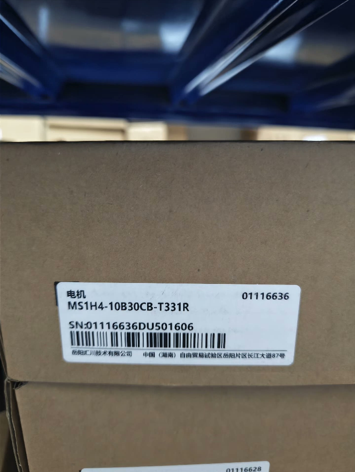

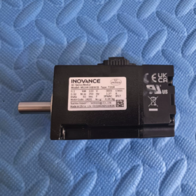
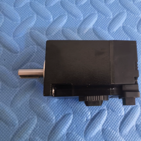
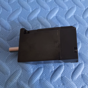
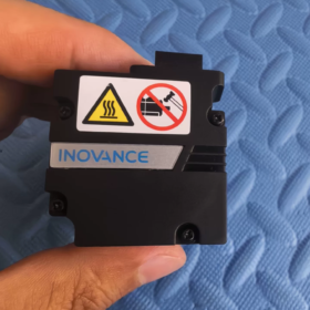
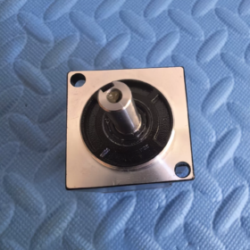
MS1H4-10B30CB-T331R
| Segment | Definiţie |
| MS1 | Seria MS1 General Servomotor |
| H4 | Inerție medie, Capacitate mică |
| 10B | Putere nominală: 10×10 = 100W (0.1kW) |
| 30C | Viteza nominală: 30×100 = 3000 rpm |
| B | Clasa de tensiune: Mono/Trifazat AC220V |
| T3 | 18-bit Multi-turn Absolut Codificator |
| 3 | Configurația arborelui: Cu calea cheii + Filet interior la capătul arborelui |
| 1 | Accesorii: Cu sigiliu de ulei, Fara frana de mentinere electromagnetica |
| R | Versiune standard cu flanșă |
Notă de distincție: A3 = encoder absolut multi-turn pe 23 de biți; T3 = encoder absolut multi-turn pe 18 biți. Cablurile sunt interschimbabile mecanic, dar rezoluția diferă; parametrii nu trebuie utilizați fără reconfigurare.
- Specificații electrice principale
| Articol | Valoare |
| Putere nominală | 100W / 0.1kW |
| Cuplu nominal | 0.32 N·m |
| Cuplul maxim | 1.12 N·m (350% Supraîncărcare) |
| Viteza nominală | 3000 rpm |
| Viteza maxima | 7000 rpm |
| Curent nominal | 1.27 O |
| Curentul de vârf | 4.78 O |
| Momentul de inerție al rotorului | 0.072 ×10⁻⁴ kg·m² |
| Dimensiunea flanșei cadrului | 40 mm |
| Codificator | 18Bit Encoder absolut multi-turn |
| Frână de oprire | Nu Echipat |
| Clasa de protectie | IP67 (Excluzând zona de etanșare a arborelui) |
| Tip de serviciu | S1 Funcționare continuă |
- Servo Drives compatibile
✅ Potriviri recomandate:
Seria SV660PS (Mainstream)
Seria SV670PS
Nu este compatibil direct cu unitățile vechi IS620. Cablul adaptor al codificatorului este obligatoriu dacă se utilizează IS620.
- Aplicații tipice
Echipament mic de poziționare, 3C echipamente de automatizare, mecanisme de transport în miniatură, platforme de reglare fină, module liniare, mașini de dozare, lamele de inspecție, mici unități de indexare.
- Comparația modelului derivat (Pentru Achizitii & Înlocuire)
MS1H4-10B30CB-A331R: 23-codificator absolut multi-turn (Versiune de înaltă precizie)
MS1H4-10B30CB-T32R: Cu frână de oprire și etanșare de ulei
MS1H4-10B30CB-T30R: Fara etansare si frana de staţionare
- Selecţie & Precauții de înlocuire
- Acest model nu are frână de oprire. Nu-l utilizați pentru sarcinile pe axa verticală; selectați varianta echipată cu frână T32R pentru aplicații verticale.
- T3 (18-pic) și A3 (23-pic) codificatoarele partajează interfețe de conector identice. Tipul de encoder trebuie reconfigurat în parametrii convertizorului după înlocuirea motorului.
- Viteza maxima 7000 rpm; Se recomandă viteza de funcționare susținută ≤6000 rpm pentru a evita creșterea excesivă a temperaturii.
- Proiectarea arborelui: Calea cheii + filet interior la capătul arborelui. Verificați dimensiunile cuplajului în timpul înlocuirii.
INOVANȚA MS1H4-10B30CB-T331R (40 Cadru, 100W, Fara frana) Dimensiuni de contur
Unitate: mm, Acest model = versiune fără frână; dimensiunile din interiorul consolelor reprezintă lungimea totală a variantei echipate cu frână T32R.
- Dimensiuni generale de montare
| Marca | Descriere | Valoare | Toleranţă |
| LC | Lățimea bazei de montare cu flanșă pătrată | 40 | Standard 40 Cadru |
| THE | Diametrul exterior al flanșei | 46 | — |
| LL | Lungimea totală a motorului (Suprafața flanșei spre capătul din spate) | 91 | Varianta cu frana: 121.5 |
| LR | Lungimea proeminenței arborelui (Fața flanșei la capătul arborelui) | 25 | ±0,3 |
| LIVRE | Diametrul arborelui de ieșire | Φ30 h7 | 0/-0.021 |
| LG | Adâncimea canalului cheie | 5 | — |
| THE | Lățimea canalului cheie | 2.5 | ±0,5 |
| LJ | Teșire la capătul arborelui | 0.5 | ±0,35 |
| LZ | Montare prin gaura | 2×Φ4,5 | Aranjat în diagonală |
| LH | Distanța centrului găurii de montare | 34.3 | — |
- Detalii arbore de ieșire (Calea cheii + Filet interior arborelui, Sufix “3” Specificația arborelui)
- Diametrul arborelui: Φ30h7
- Dimensiunea tastelor paralele: Latime 2,5 mm, Adâncime 5 mm
- Capătul arborelui: Orificiu filetat intern (pentru cuplare inel de reținere/poziționare)
- Lungimea extensiei arborelui: 25mm
- Sarcini admisibile pe arbore
Sarcina radială admisă: 120 N (la capătul arborelui)
Sarcina axială admisă: 40 N
⚠️ Suprasarcina va accelera uzura rulmentului și va scurta durata de viață.
- Greutate
MS1H4-10B30CB-T331R (Fara frana): 0.75 kg
Derivatul T32R (Cu frana): 0.98 kg
- Note de asamblare a cheilor
- Clasa de protectie IP67: Regiunea de etanșare a arborelui și conectorii electrici sunt excluse din clasificarea IP67. Evitați scufundarea permanentă în apă.
- Montare: Montare flanșă frontală; dispozitiv de fixare recomandat M4, cuplu de strângere 1,2~1,5 N·m
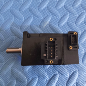
- Conectori: Conectorii de alimentare și encoder sunt aranjați lateral în spatele motorului. Rezervă autorizație în proiectarea echipamentelor.
- Avertisment privind schimbul mecanic: Varianta echipată cu frână T32R lungime totală 121,5 mm; nu poate fi schimbat direct fără modificarea cadrului mecanic.
- Numerele de piesă potrivite pentru cablu (Achizitie de piese de schimb)
Cablu de alimentare: S6-L-M04-xxx (40-cablu de alimentare cadru)
Cablu codificator pentru absolut multi-turn pe 18 biti: S6-E-T3-xxx
Nu este compatibil direct cu cablurile definite pentru codificatorul A3.
INOVAȚIE MS1H4-10B30CB-T331R (40 Cadru, 100W, Fara frana) Specificație completă de instalare
- Tip de montare de bază
Montare standard: Montare cu flanșă frontală (Flanșă IEC B3)
Este acceptată numai montarea pe flanșă; fără structură de montare pe picior. Dimensiunea flanșei pătrate 40 mm.
Sufixul R = Versiune standard cu flanșă; Arbore solid cu cheie paralelă și filet interior la capătul arborelui.
- Specificații de fixare (Critic)
- Orificii de montare: 2 distribuite diagonal Φ4,5 prin găuri
- Bolt recomandat: Șurub cu cap cu cap hexagonal M4 (Gradul ≥8,8)
- Cuplu de strângere standard: 2.4 N·m
✅ Regula de funcționare: Strângeți în diagonală în mai multe treceri. Evitați strângerea completă pe o singură parte pentru a preveni deformarea flanșei.
- Montarea planului de referință: Suprafața flanșei frontale a motorului; planeitate ≤0,02mm.
- Orientari de montare permise
| Orientarea montajului | Permisibilitate | Cerințe obligatorii |
| Montaj orizontal (Arbore Orizontal) | ✅ Recomandat | Disiparea optimă a căldurii; fără constrângeri suplimentare |
| Arborele de montare verticală în jos (Încărcare suspendată) | ✅ Permis | Rezervați spațiu liber pentru conectorii de cablu; Frână de oprire – NU suspendați sarcinile când alimentarea este oprită. |
| Arborele de montare verticală în sus (Încărcare cu fața în sus) | ⚠️ Nu este recomandat pentru funcționare pe termen lung | Îmbătrânire accelerată a garniturii de ulei din față; aplicabil numai pentru echipamente cu ciclu scurt. |
| Mont înclinat (Orice unghi) | ✅ Permis | Aranjați conectorii în jos pentru a evita pătrunderea apei condensate. |
Avertisment important: Nu este montată frână de oprire electromagnetică. Strict interzis pentru ridicarea sarcinilor verticale. Selectați modelul T32R echipat cu frână pentru axe verticale!
- Specificații de conectare a arborelui motor la sarcină
4.1 Recapitulare parametrul arborelui
Diametrul arborelui Φ30 h7; extensie ax 25mm; latime cheie paralela 2,5 mm; filet interior la capătul arborelui.
4.2 Regula de instalare a cuplajului
❌ Nu loviți niciodată capătul arborelui motor direct cu ciocanul!
Impactul va deteriora inelul magnetic al codificatorului și va dezactiva permanent motorul.
✅ Practică corectă: Utilizați unelte de montare hidraulice, ansamblu termic (temperatura ≤80℃), sau metoda cricului cu șurub pentru cuplarea prin presare.
4.3 Toleranță la coaxialitate
Offset radial maxim admis: ≤0,03 mm
Dezaliniere unghiulară maximă: ≤0,5°
Cuplaj recomandat: Cuplaj flexibil cu falci / Cuplaj cu diafragmă
Nealinierea excesivă provoacă vibrații, uzură prematură a rulmenților și zgomot de mare viteză.
4.4 Sarcină externă admisă continuă
Sarcina radială admisă la capătul arborelui: 120 N
Sarcina axială admisă la capătul arborelui: 40 N
Transmisia cu curea și transmisia prin angrenaje generează forțe radiale continue; calculul sarcinii este obligatoriu pentru a evita depășirea limitelor.
- Disiparea căldurii & Autorizație de instalare
- Metoda de răcire: Răcire prin convecție naturală. Rezervați ≥30 mm spațiu liber în jurul aripioarelor de răcire.
- Nu atașați partea din spate a motorului direct pe tablă sau pe capacul închis.
- Reduceți puterea motorului când temperatura ambiantă depășește continuu 40°C; reduce puterea pentru altitudine >1000m.
- Temperatura maximă admisă a suprafeței carcasei în timpul funcționării: ≤120°C.
- Conector & Reguli de rutare a cablurilor
- Conectorii de alimentare și de codificator sunt amplasați pe partea din spate a motorului. Rezervați spațiu de mișcare a cablului în design mecanic.
- Detensionarea cablului: Instalați clema de cablu adiacent conectorilor pentru a preveni tensiunea cauzată de conectorii care trag greutatea cablului.
- Separarea cablajului: Cabluri de alimentare separate și cabluri ecranate pentru codificator; menține o distanță paralelă ≥30cm. Încrucișați cablurile la 90° acolo unde este posibil.
- Impermeabil pentru conectori: Asigurați-vă că ștecherele sunt complet blocate. Evitați conectorii orientați în sus din interiorul echipamentului pentru a preveni acumularea de apă. Clasamentul IP67 se aplică numai carcasei motorului; conectorii nu sunt sigilati IP67.
- Specificații de împământare
- Conectați fiabil terminalul PE al carcasei motorului la pământ de protecție.
- Straturile de ecranare ale cablului de alimentare și al cablului codificatorului vor fi împământate la ambele capete la bara de împământare a cabinetului conform standardului Inovance.
- Rezistenta la sol <100Ω pentru a preveni deviația poziției codificatorului și defecțiunile de comunicare cauzate de interferențe electromagnetice.
- Interdicții de instalare (Reguli obligatorii)
- Sudarea sau sudarea în puncte pe carcasa motorului este interzisă; temperatura ridicată va distruge codificatorul intern.
- Slefuirea sau prelucrarea pe flanșa și arborele motorului este interzisă.
- Evitați o oprire prelungită a motorului.
- Preveniți spălarea continuă a etanșării arborelui cu lichid de tăiere sau contaminare cu ulei.
- Nu ridicați/deplasați motorul prin cabluri sau conectori în timpul manipulării; prindeți numai carcasa flanșei.
- Procedura standard de instalare
- Curățați baza de montare, îndepărtați bavurile și așchiile de metal.
- Atașați flanșa motorului la suprafața de montare, introduceți șuruburi M4 și aplicați pre-strângerea diagonală.
- Asigurați motorul temporar și asamblați cuplajul.
- Reglați poziția motorului și verificați coaxialitatea cu cadran.
- Strângeți șuruburile la cuplul specificat de 2.4 N·m în succesiune diagonală.
- Instalați suporturi pentru cablu, conectați cablul de alimentare și cablul codificatorului.
- Verificați dacă există interferențe mecanice și riscuri de tensionare a cablurilor înainte de punerea în funcțiune.





NH42-63-318x560.png "Comutatoare de transfer automat de tip PC CHINT (ATS)NH42-63/4SZ")



