 Контактор,автоматический выключатель,датчик,Кодер,ПЛК,Конвертер

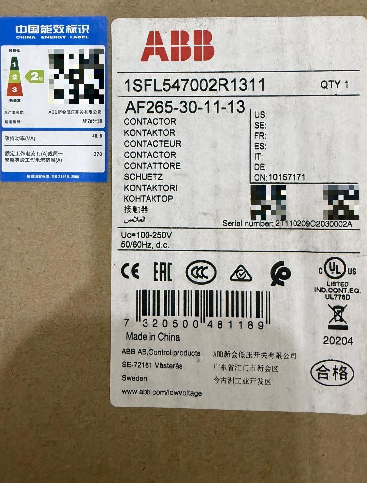

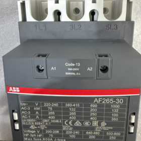
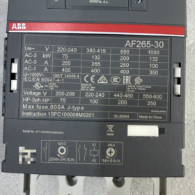
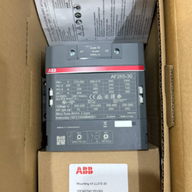
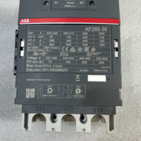
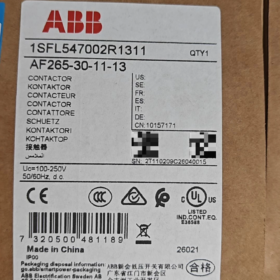
Заказ №.: 1SFL547002R1311;Материал №.: 10157171
Ряд: AF-Series 3-Pole Contactor with Universal AC/DC Electronic Coil
- Расшифровка кода модели
| Модельный сегмент | Описание |
| ИЗ | AF‑series, wide‑range universal AC/DC electronic coil, built‑in surge suppression; no external RC network or varistor required |
| 265 | Rated operational current 265A under AC‑3 @400V; Обычный тепловой ток (АС‑1): 400А |
| 30 | 3полюс, all main contacts Normally‑Open (НЕТ); no main Normally‑Closed (Северная Каролина) контакты |
| 11 | Built‑in auxiliary contacts: 1NO +1NC |
| ‑13 | Coil code: 100‑250 V AC/DC (50/60 Гц + DC compatible) |
✅Key Features: Single coil supports AC 100-250 V & DC 100-250 V; high tolerance to voltage fluctuation; low holding power consumption; silent operation.
- Основные электрические характеристики
| Элемент | Ценить |
| Number of Main Poles | 3П (3 main NO contacts) |
| Motor current AC‑3 (400 В) | 265 А; Motor rating 132 kW |
| Resistive load AC‑1 | 400 А |
| Номинальное напряжение изоляции Ui | 1000 В(МЭК) /600 В(UL) |
| Номинальное импульсное выдерживаемое напряжение Uimp | 8 кВ |
| Управляющее напряжение катушки | 100‑250 V AC/DC 50/60 Hz‑DC |
| Вспомогательные контакты | 1НО+1НЗ (front‑mounted, non‑removable) |
| Механическая выносливость | 5 million operating cycles |
| Максимальная рабочая частота | 300 операций/час |
| Pick‑up voltage | 80 % of lower coil rated voltage; Drop‑out voltage 55 % of lower coil rated voltage |
III. Относящийся к окружающей среде & Механические параметры
| Элемент | Ценить |
| Рабочая температура окружающей среды (without thermal relay) | ‑40 ℃ ~ +70 ℃; ‑25 ℃ ~ +55 ℃ with thermal overload relay |
| Температура хранения | ‑40 ℃ ~ +70 ℃ |
| Altitude without derating | ≤3000 m; derating required above 3000 m |
| Габаритные размеры (Ш×В×Г) | 140 mm × 225 mm × 180 mm |
| Вес нетто | 3.9 кг |
| Тип терминала | Главная цепь: шинопровод / bolt‑type terminals; Схема управления: винтовые клеммы |
| Способ монтажа | Vertical DIN‑rail or back‑plate screw mounting, sideways or inverted mounting strictly prohibited |
Сертификаты: CCC, CE, UKCA, ЕАС, DNV marine certification; Функциональная безопасность: уровень безопасности 2, ISO13849-1 Cat.B.
- In-Depth Operating Principle
AF-series contactors adopt electronic rectifier-type coil, different from traditional AC contactors:
- Apply 100-250 V AC or DC to A1/A2; internal electronic circuit rectifies input to DC for driving electromagnetic coil.
- High instantaneous power for pull-in, then switch to low DC holding power; much lower coil heating than conventional AC coils.
- On-board built-in TVS surge absorber dissipates back-EMF upon coil de-energization. Do NOT connect external RC networks or varistors in parallel; external devices may cause malfunction or permanent damage.
- DC-magnetized armature eliminates 50 Hz AC hum noise.
Определение терминала
Main circuit line-side: 1Л1, 3Л2, 5Л3; load-side: 2Т1, 4Т2, 6Т3
Катушка: А1, А2 (non-polar for AC & округ Колумбия)
Вспомогательные контакты: 13-14 (НЕТ); 21-22 (Северная Каролина)
- Стандартный упаковочный лист & Дополнительные аксессуары
Standard Delivery
- AF265-30-11-13 Contactor Unit ×1
- Руководство по продукту, certificate of compliance
❗Not included: Тепловое реле перегрузки, механическая блокировка, auxiliary add-on blocks, terminal safety shield.
Separately-ordered Accessories
| Аксессуар | Функция |
| TA275 DU | Соответствующее тепловое реле перегрузки (80‑275 A) |
| CAL19‑11 | Side‑mount auxiliary contact block (1НО+1НЗ) |
| VM265 | Механическая блокировка (for reversing duty) |
| AF‑MTP | Main circuit terminal protective cover |
- Cross-Brand Compatibility & Справочник по замене
⚠️Verify coil rating 100-250 VAC/DC and AC-3 265 A rating before replacement.
| Оригинальная модель | Direct‑fit Equivalent | Примечания |
| АББ AF265‑30‑11‑13 | A265‑30‑11 (Legacy EH265) | Old EH‑series coils are AC‑only / DC‑only; coils cannot be interchanged directly |
| Competitor Equivalents | Siemens 3RT1066‑6AP36; Schneider LC1D245M7 | No native 100‑250 V wide‑range AC/DC coil for Siemens/Schneider; select correct coil variant |
VII. Типичные сценарии применения
- Вентилятор & pump large-size motor starting (ОВК, central air-conditioning, очистка воды)
- Воздушный компрессор, extruder motor control (110-132 kW three-phase motors)
- Capacitor bank switching (match AC-1 400 A rating)
- Forward/reversing and star-delta main circuits
- Морской & export-oriented equipment: compatible with global control voltages (120 VAC /220 VAC universal)
VIII. Подводные камни выбора & Жесткие ограничения
- ❌Do NOT add external surge suppressors (RC networks, varistors, diodes). Built-in surge protection provided; external devices cause coil damage or failure to open.
- ❌Sideways or inverted mounting forbidden; only upright vertical installation permitted.
- ❌Derating is mandatory above 3000 m altitude; otherwise contact overheating and burnout may occur.
- ❌Not suitable for high-frequency switching (>300 операций/час); use vacuum contactors for frequent-duty applications.
- ✅Wide control voltage tolerance: reliable pull-in within 80-250 V.
- Поиск неисправностей
| Симптом | Первопричина | Средство |
| Contactor will not pull‑in | No voltage across A1‑A2; свободные соединения; internal electronic coil board failure | Measure voltage A1‑A2; retighten terminals; заменить блок целиком (AF coil cannot be replaced separately) |
| болтовня / intermittent pull‑in | Control voltage below 80 % minimum limit; excessive power‑supply ripple | Ensure input voltage ≥80 V; rule out insufficient PLC output drive capacity |
| Excessive main‑circuit terminal heating | Insufficient bolt torque; перегрузка; contact erosion / burning | Retorque busbar bolts; check load current; replace contactor for severe contact ablation |
| Contacts remain closed after de‑energization (прилипание) | Main contact welding; residual induced voltage on control wiring | Investigate short‑circuit conditions on load side; eliminate induced residual voltage in control cables |
Важный: The AF-series coil electronic board is integrated inside the unit; coil faults require complete contactor replacement; spare coil assemblies are not available.
ABB AF265-30-11-13 Operating Instructions (Compiled Manual)
Corresponding original manual document No.: 1SFC100008M0201, applicable frame size: AF190-205-265-305-370 series
Заказ №.: 1SFL547002R1311;Номинал катушки: 100-250 В переменного/постоянного тока
⚠️Предупреждение о безопасности.: Installation and commissioning must be performed by qualified electrical personnel. Disconnect all upstream power supply prior to any wiring or maintenance work. Do NOT apply high-voltage dielectric test across A1/A2 coil terminals; electronic coil board will suffer permanent breakdown damage.
Оглавление
- Обзор продукта
- Модель & Определение терминала
- Характеристики установки
- Электропроводка & Момент затяжки
- Coil Operating Instructions (AF Electronic Coil Key Notes)
- Commissioning Procedure
- Accessory Mounting
- График технического обслуживания & Объекты проверки
- Устранение неполадок
- Запрещенные операции
- Access to Original PDF Manual
- Обзор продукта
AF265-30-11-13 is a 3-pole contactor with integrated wide-range electronic coil and built-in surge suppression. External RC / varistor suppressors are prohibited.
AC-3-400 V: 265 А, motor rating 132 kW
AC-1 resistive: 400 А
Встроенные вспомогательные контакты:1НЕТ(13-14)+1Северная Каролина(21-22)
Номинал катушки:100-250 В переменного/постоянного тока; pull-in ≥80 %Uc; drop-out ≤55 %Uc
Механическая выносливость:5 миллион циклов; max operating frequency 300 операций/час
Рабочая температура:-40 ℃~+70 ℃ (without thermal relay); no derating ≤3000 m altitude.
- Определение терминала
| Схема | Терминал №. | Описание |
| Main circuit line‑side | 1Л1, 3Л2, 5Л3 | 3‑phase power input |
| Main circuit load‑side | 2Т1, 4Т2, 6Т3 | Мотор / load connection |
| Катушка | А1, А2 | Non‑polar for AC/DC; rated for 100‑250 V AC/DC |
| Built‑in auxiliary NO | 13-14 | Нормально открытый |
| Built‑in auxiliary NC | 21-22 | Normally‑Closed |
CAL19-11 auxiliary add-on block can be fitted on the left side of unit.
- Характеристики установки
- Ориентация монтажа: vertical upright installation only (main terminals vertical up-down). Sideways or inverted mounting is strictly forbidden.
- Two installation options:
Back-plate screw fixing: 4 pcs M8 bolts
DIN35 mm rail mounting (For large-frame AF265, screw mounting is preferred over rail-mount).
- Cabinet heat dissipation: Multiple units can be mounted side-by-side without gaps; no derating up to 70 ℃ ambient. Derating is mandatory for altitude >3000 м.
- Suggested minimum cabinet dimension: ≥900×750×300 mm, to ensure adequate top-bottom ventilation.
- Prevent metal chips and drilling dust from entering contactor enclosure during installation.
- Электропроводка & Момент затяжки (Most overheating originates from insufficient torque)
| Расположение терминала | Bolt Size | Recommended Tightening Torque | Требования к кабелю |
| Main circuit L/T terminals | М12 | 24 Н·м | Copper busbar / ATK300 lugs; 75 ℃ rated copper conductors; direct aluminum conductor connection prohibited |
| Coil A1‑A2 | М4 | 1.2‑1.5 N·m | 0.75‑2.5 mm² copper wire |
| Вспомогательные контакты | М4 | 1.2 Н·м | 0.75‑2.5 mm² copper wire |
ATK300 crimped lugs are recommended for main circuit. Fit AF-MTP terminal safety shield over bare live conductors for touch-protection.
- Coil Operating Instructions (AF Electronic Coil Key Notes)
- A1/A2 coil terminals are non-polar; either AC or DC 100-250 V may be applied directly.
- Built-in on-board TVS surge suppression. External RC snubber, varistor or freewheeling diode are strictly forbidden. External surge devices will burn coil board or cause failure to open.
- Втягивание: reliable closing ≥80 % ×100 V = 80 V.
- Drop-out: reliable opening ≤55 %Uc.
- Low holding power consumption; silent operation, no hum.
- ❗Electronic coil board is integrated within main unit. Coil cannot be replaced separately; full-unit replacement required upon coil failure.
- Dielectric withstand test: Never perform hipot test across A1-A2 coil terminals; will destroy electronic circuit.
- Commissioning Steps
- All power disconnected; verify full wiring and torque values; confirm arc-chamber cover is fully seated and intact.
- Confirm control supply voltage matches -13 coil rating (100-250 VAC/DC).
- Keep main 3-phase supply disconnected; energize only control circuit for no-load functional test:
Apply voltage to A1-A2: contactor shall pull-in promptly; de-energize for immediate release without chattering.
Verify auxiliary contact logic: 13-14 открыть/закрыть, 21-22 close/open as expected.
- Proceed to energize main power only after successful no-load test, perform loaded trial-run.
- Run under full load for minimum 30 minutes; measure terminal temperature rise; acceptable housing temperature rise ≤60 K.
- Accessory Mounting
- CAL19-11 (side-mount auxiliary block): Slide into left-hand side slot of contactor until fully latched; adds 1NO+1NC contacts.
- VM265 mechanical interlock: for forward-reverse interlock application; two contactors required as pair.
- TA275-DU thermal overload relay: bottom-mount installation; relay operating temperature range -25~+55 ℃.
- AF-MTP main-circuit terminal safety shield, prevents accidental touch of live busbars.
All accessories are separately-ordered, not included as standard delivery.
- Периодическое техническое обслуживание & Инспекция
Perform only with full power disconnected! Интервал технического обслуживания: every 12 months for clean environment; every 6 months for dusty / high-vibration conditions.
- Retighten all main-circuit terminals to specified torque.
- Inspect arc-chamber cover for cracks, carbon deposits or metal powder accumulation; replace arc-chamber for severe burning.
- Inspect main contact erosion; replace complete unit for heavy wear or contact welding. No separate contact spare-parts available for AF265.
- Clean external dust. Do NOT blow compressed-air directly into enclosure, metal dust may damage internal coil electronics.
- Verify cabinet ambient temperature and unobstructed ventilation paths.
- Functional test of auxiliary contact switching.
Примечание: AF190-AF370 frame units have no serviceable separate contact assemblies; full-unit replacement required upon contact damage.
- Troubleshooting Table
| Симптом | Причина | Средство |
| Contactor will not pull‑in | No voltage A1‑A2; свободные соединения; internal electronic coil failure | Measure A1‑A2 voltage; retighten terminals; replace full unit |
| болтовня / repeated bouncing | Control voltage below 80 % minimum; insufficient PLC output drive; induced residual voltage in control wiring | Проверьте напряжение питания; upgrade PLC drive capacity; eliminate induced residual voltage |
| Will not open after de‑energization (прилипание) | Main‑contact welding; residual induced voltage on control circuit; incompletely‑removed external surge components | Locate load‑side short‑circuit fault; eliminate induced voltage; fully remove external RC / varistor devices |
| Excessive heating at main terminals | Insufficient bolt torque; undersized cable / шинопровод; overload condition | Retorque fasteners; recalculate conductor ampacity; measure actual load current |
| Coil burns immediately upon energization | Hipot test applied to A1‑A2; external surge devices; supply voltage exceeds 250 V upper limit | Forbid hipot on coil terminals; remove external surge components; limit control voltage within rated 100‑250 V range |
- Запрещенные операции
❌Sideways or inverted mounting forbidden;
❌Hipot / megger test on A1/A2 coil terminals forbidden;
❌External RC snubber, varistor or freewheeling diode forbidden;
❌Do not exceed 300 operations/hour switching frequency;
❌Operation without derating for altitude >3000 m forbidden;
❌Do not attempt to disassemble internal coil electronic assembly; no serviceable spare-parts.
- Access to Original PDF Manual
- Visit ABB official product webpage, search order number 1SFL547002R1311 → Downloads section, download datasheet and Operating Instructions.
- Document reference numbers: Operating instruction: 1SFC100008M0201 (multilingual including Chinese); Service manual 1SFC101044M0201.







NH42-63-318x560.png "Автоматические переключатели резерва типа PC CHINT (АТС)НХ42-63/4СЗ")



