 Контактор,автоматический выключатель,датчик,Кодер,ПЛК,Конвертер

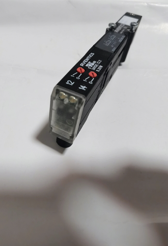

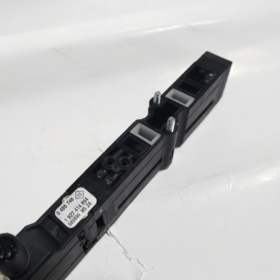
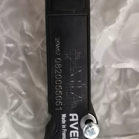
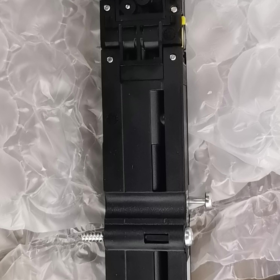
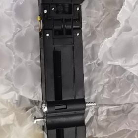
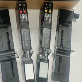
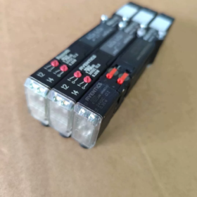
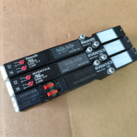
Бош Рексрот’s pneumatics division has been rebranded as AVENTICS, while the original part numbers remain unchanged.
Full Model Alias: HF03-3/2CC-024округ Колумбия
Функция клапана: Dual 3/2-way solenoid valve (2×3/2, Нормально закрытый + Нормально закрытый)
- Ключевые характеристики
| Элемент | Параметр |
| Номер детали | 0820055102 (0 820 055 102) |
| Valve Construction | 2×3/2-way spool valve, positive overlapping, soft seal |
| Напряжение питания | 24 В постоянного тока; Допуск по напряжению: -15% ~ +20% |
| Power Consumption per Coil | 0.35 Вт (низкая мощность) |
| Nominal Flow Qn | 850 л/мин |
| Operating Air Pressure | -0.9 ~ 10 бар; Minimum pilot pressure: 2.5 бар (externally piloted) |
| Середина | Сухой сжатый воздух; Particle size ≤5 μm, lubrication optional |
| Окружающий & Medium Temperature | 0 ℃ ~ +50 ℃ |
| Монтаж | Subplate mounting for valve manifold; Ширина: 16 мм |
| Ручное управление | Non-detent manual test button |
| Сертификация | UR certified |
| Масса | Приблизительно. 85 г |
- Интерпретация кода модели
Ряд 0820 = HF03-LG modular valve manifold solenoid valve
0820055xxx: HF03 series compact electrically operated directional valve
102: Function code → 2×3/2 CC (two independent 3/2-way, нормально закрытый)
Electrical definition: Dual coils, independently control two separate 3/2 pneumatic circuits.
- Pneumatic Function Description
Two independent 3/2-way valves:
Обесточен (coil off): Порт 1 к 2 blocked; Порт 2 connected to exhaust port 3
Заряженный (coil on): Порт 1 connected to port 2; Порт 3 blocked
Типичные применения: Vacuum control, dual single-acting cylinder control, widely fitted on Homag woodworking machinery.
- Совместимость & Matching Information
- Coils: Coils are integrated into valve body, supplied as one assembly. Cannot be interchanged with coils of other HF03 5/2-way valves.
- Base Plate: Compatible with HF03 series integrated valve manifold subplates.
- Электрический интерфейс: Multi-pin bus / collective wiring for valve manifolds; no separate cable outlet.
- Reference for Similar Models
0820055052: 5/2-way single-solenoid valve
0820055102: 2×3/2 dual 3/2-way valve (эта модель)
- Выбор & Рекомендации по устранению неполадок
- External pilot pressure ≥2.5 bar is mandatory. Insufficient supply pressure causes failure to switch.
- Medium temperature must not drop below 0 ℃ to prevent condensate ice from jamming the spool.
- Positive overlapping spool design → not suitable for high-frequency micro-flow vacuum holding applications.
- Do NOT directly replace with a 5/2-way valve; pneumatic function circuits differ completely.
- Install a 5 μm precision filter upstream; dust contaminants easily cause spool sticking.
- Типичные применения
Woodworking CNC machining centers (Homag), automated assembly lines, vacuum handling systems, упаковочное оборудование, compact valve manifold pneumatic control.
Если требуется, я могу предоставить:
✅ Simplified pneumatic circuit symbols
✅ Excerpts from official datasheet
✅ List of functionally equivalent replacement models
✅ Inquiry for matching valve manifold base plate part numbers
Operating Principle of Aventics (Рексрот) 0820055102
Полное обозначение модели: 0820 055 102 HF03, 2×3/2 CC Dual 3/2-Way Solenoid Valve
Basic Construction: Pilot-operated spool valve, soft sealing, two independent solenoid coils, two isolated 3/2 pneumatic circuits, externally piloted air supply
- Structural Breakdown
- Main Spool Assembly: Two independent built-in spools (Channel A / Channel B)
- Two independent solenoid pilot units (Катушка 1 / Катушка 2, 24 В постоянного тока)
- Common main supply port (Порт 1, shared for working air and pilot air)
- Pneumatic port allocation:
Канал 1: 1 (Поставлять), 2 (Load Output), 3 (Exhaust)
Канал 2: Separate independent set of ports 1, 2, 3
CC abbreviation: Нормально закрытый (default closed position)
- Core Operating Principle (Externally Piloted Spool Valve)
⚠️ Critical prerequisite: Minimum external pilot pressure ≥2.5 bar for reliable valve switching
The built-in solenoid only controls a miniature pilot air circuit. The coil does not drive the main spool directly; compressed air pressure actuates the main spool.
State 1: Both coils de-energized (default resting position)
Return springs hold both spools at home position.
Pneumatic status (identical for both circuits):
✅ Supply port 1 ➜ Blocked, air supply to load port 2 cut off
✅ Load port 2 ➜ Connected to exhaust port 3
👉 Load pressure relieved; applicable for single-acting spring return cylinder retraction, vacuum generator shutdown, vacuum cup air blow-off.
State 2: 【Coil 1 Заряженный, Катушка 2 De-Energized】
Катушка 1 energizes, opens the micro pilot air passage;
Pilot air pressure pushes the first main spool to switch position.
Pneumatic switching for Circuit 1:
✅ Supply port 1 ➜ Connected to load port 2
✅ Exhaust port 3 ➜ Blocked
👉 Air supply pressurizes the load;
Схема 2 remains unchanged and stays exhausted.
State 3: 【Coil 2 Заряженный, Катушка 1 De-Energized】
Only the second spool switches; Схема 2 receives air supply, Схема 1 remains exhausted.
⚠️ Важно: Two coils operate independently without mechanical linkage. One circuit can supply air while the other exhausts for fully separated dual control.
❌ Avoid continuous simultaneous energization of both coils. No hardware interlock; software interlock must be implemented in machine control program.
- Pneumatic Function Diagram Description (2×3/2 NC)
For each individual circuit:
Обесточен: 2 ↔ 3 (Exhaust), Порт 1 blocked
Заряженный: 1 ↔ 2 (Поставлять), Порт 3 blocked
- Pilot-operated vs Direct Acting (Root Cause of Spool Jamming)
- Direct acting valve: Electromagnetic force drives spool directly with limited thrust.
- This externally piloted valve: Solenoid only controls low-flow pilot air; supply air pressure drives the larger main spool.
Преимущества: Compact dimension, высокая пропускная способность (850 л/мин), low coil power consumption (0.35 Вт).
Disadvantage: The valve cannot switch at all if supply pressure falls below 2.5 бар, the most common on-site fault.
- Расход воздуха & Spool Sequence (Simplified for Single Circuit)
Compressed air supply → Common inlet Port 1
Катушка обесточена: Spring pushes spool → Port 2 links to 3, load exhausts
Катушка под напряжением: Pilot pressure overcomes spring force and shifts spool → Port 1 links to 2, load pressurized
- Typical Working Scenario (Homag Woodworking Machinery)
Two independent vacuum suction cups controlled separately:
Coil energized → Air supply to vacuum generator, suction cup generates vacuum for workpiece holding
Coil de-energized → Suction cup exhausts, vacuum released and workpiece unloaded
- Fault Correlation for On-Site Troubleshooting
- Supply pressure <2.5 bar → Insufficient pilot thrust, spool cannot shift, valve fails to switch despite powered coil
- Вода & contaminants in compressed air → Scaling on spool sliding surfaces, spool seizure
- Long-term operation with dry, non-lubricated air → Degraded lubrication, slow switching response
- Single coil burnout → Corresponding circuit fails to switch, the second circuit continues normal operation
I can provide upon request:
- Text-based pneumatic flow schematic
- Electrical control wiring logic explanation
- Performance comparison with other 0820055 series 5/2-way valves
Критическое различие (Распространенное заблуждение)
Many technicians mistake this for a double-solenoid 5/2-way valve.
0820055102 is NOT a 5/2 клапан! It integrates two fully independent 3/2-way valves within one 16 mm valve slice. The two pneumatic circuits are completely isolated with no interconnection.
Complete Application Scenario Analysis of Rexroth/Aventics 0820055102 (HF03-LG 2×3/2CC 24VDC)
Pre-Review of Core Characteristics
Valve specifications: Integrated two independent normally closed 3/2-way valves (isolated pneumatic circuits), externally piloted, 16 mm width for valve manifold mounting, two separate 24 VDC coils.
Pneumatic function per circuit:
Катушка обесточена: 2↔3 (Exhaust), Порт 1 blocked; Катушка под напряжением: 1↔2 (Поставлять), Порт 3 blocked.
Основные преимущества: One valve slice delivers dual independent control, saving manifold installation space; низкая мощность 0.35 W coil; flow rate up to 850 л/мин; compatible with both positive pressure pneumatic circuits and negative vacuum circuits.
Ограничения: Requires minimum 2.5 bar pilot pressure for switching; positive overlapping spool not suitable for high-frequency, long-duration vacuum holding requiring zero leakage.
Largest installed base: Homag CNC woodworking machining centers, the most classic OEM application.
- Деревообрабатывающее оборудование (Primary Application)
Homag CENTATEQ CNC Machining Centers, Edgebanders, Sanders
Working Case 1: Zoned Vacuum Cup Control (Наиболее широко используемый)
One valve controls two independent suction cup groups:
Катушка 1 energized → Activate vacuum generator supply, vacuum builds up for panel holding
Катушка 1 de-energized → Suction cup exhausts, vacuum broken, workpiece released
The second coil controls another set of suction cups separately. Enables selective activation of vacuum zones for different workpiece sizes, reduces vacuum energy consumption and prevents thin panel deformation.
✅ Benefit: Dual independent control saves manifold slot space compared to installing two separate 3/2-way valves.
Working Case 2: Single-acting Clamping Cylinders, Material Stops, Position Pins
Woodworking equipment extensively uses spring return single-acting cylinders:
Катушка под напряжением: Air supply extends cylinder (position pin pop-up, stop barrier raised)
Катушка обесточена: Air exhausts, spring retracts cylinder
One valve controls two separate positioning cylinders.
Working Case 3: Blow-off for Dust Removal & Table Cleaning
One circuit controls vacuum suction cups, the second controls air blow nozzles. After machining completes, cups release workpieces and nozzles blow away wood chips.
- Automated Packaging Machinery
- Vacuum Pick & Place Systems
Two independent vacuum cups for alternating picking of cartons, boxes and plastic films; one suction circuit active, one standby.
- Single-acting Clamps & Material Stops
Limit stops and side push positioning mechanisms (spring return cylinders) on packaging conveyor lines.
- Bag Opening via Air Blowing
One circuit grips film by vacuum, the second supplies positive air pressure to open plastic bags.
⚠️ Selection Reminder: High-speed horizontal packaging machines requiring stable long-term vacuum holding are not recommended. Positive overlapping spool creates minor internal leakage leading to gradual vacuum decay.
- Non-Standard Automation Assembly Lines, 3С & Electronics Equipment
- Small spring ejectors and material hold-down mechanisms (цилиндры одностороннего действия)
- Dual-station vacuum handling modules: Separate suction cups for alternating loading/unloading
- Auxiliary pneumatic switching and purge circuits for airtight testing
Suitable for PCB transportation, plastic component assembly and small workpiece handling.
Environment requirement: Clean supply air; install 5 μm upstream filter for dusty production sites.
- Логистическая сортировка & Panel Handling Equipment
- Zoned vacuum cup control at the end effector of panel, glass and carton handling robots
- Pneumatic diverting barriers on sorting conveyors (цилиндры одностороннего действия)
- Stoppers on transport lines.
- Пластиковые инъекции & Резиновые машины
- Mold air blow circuits for part ejection
- Small vacuum cups for removing molded components
- Single-acting ejector pin control.
Recommended Pneumatic Wiring Schemes
Схема А: Dual Independent Vacuum Generator Control (Homag Standard Wiring)
Common Port 1: Подача сжатого воздуха
Output Port 2: Air supply inlet of vacuum generator
Exhaust Port 3: Equipped with silencer
Coil energized → Vacuum generator operates, suction cup holds workpiece; Coil de-energized → Vacuum stops, workpiece released naturally.
Схема Б: Control of Two Single-Acting Spring Return Cylinders
Common Port 1: Air supply
Output Port 2: Cylinder inlet
Порт 3: Exhaust
Cylinder extends when coil energized; retracts by spring when de-energized.
Схема С: One Circuit for Vacuum Suction + One Circuit for Blow-off (Расширенная конфигурация)
Канал 1: Control vacuum generator (workpiece holding)
Канал 2: Independent positive-pressure blow circuit (fast vacuum break to avoid workpiece adhesion)
Prohibited Applications | Подводные камни выбора
- Cannot directly drive double-acting cylinders
Double-acting cylinders require 5/2-way valves. A 2×3/2 valve cannot achieve reciprocating cylinder motion – a frequent engineering mistake.
- Long-duration high-vacuum sealed chamber holding
Positive overlapping spool has minor internal leakage; vacuum pressure decays gradually over time, unsuitable for sealed vacuum chamber long-term pressure retention.
- Continuous supply pressure below 2.5 бар
External pilot design results in insufficient thrust to shift spools; valve receives power but fails to actuate.
- Температура окружающей среды <0 ℃, high humidity with heavy condensate
Ice formation from condensed water causes spool sticking; a refrigerated dryer for compressed air is mandatory.
- Strong corrosive acidic gas environments
Standard NBR rubber seals are incompatible with corrosive media.
Why OEM Machine Builders Prefer 0820055102 Over Two Separate 3/2-Way Valves?
- Save manifold installation space: One 16 mm slice delivers dual control, shortening valve manifold length and reducing control cabinet size.
- Unified common air supply passage simplifies manifold internal air routing.
- Standardized base plate design simplifies centralized wiring.
- Modular HF03 valve manifold compatible with fieldbus systems (multi-pin connector, Profibus etc.), suitable for high-end Homag CNC equipment.
Functional Replacement Reference (Spare Part Exchange)
Direct replacement prerequisite: HF03-LG series valve manifold base plate
Оригинальный номер детали: 0820055102 (unique standard model)
NOT directly interchangeable: Other 0820055 series 5/2-way valves (например. 0820055052) due to different pneumatic functions.
I can supply upon request:
- Standard pneumatic circuit drawing for vacuum cup Homag configuration
- Timing sequence control logic for Homag CNC
- Troubleshooting checklist for common faults under different working conditions





NH42-63-318x560.png "Автоматические переключатели резерва типа PC CHINT (АТС)НХ42-63/4СЗ")



