 คอนแทคเตอร์,เบรกเกอร์,เซ็นเซอร์,ตัวเข้ารหัส,บมจ,ตัวแปลง

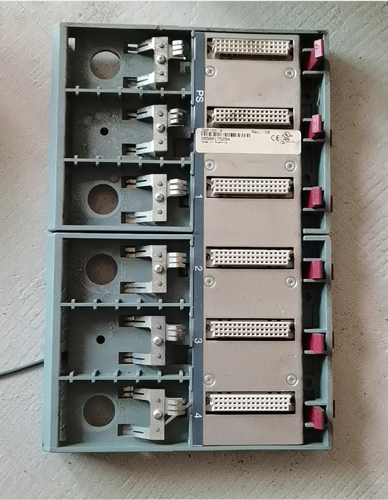

ข้อมูลพื้นฐาน
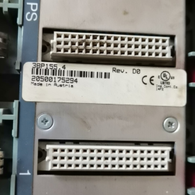
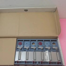
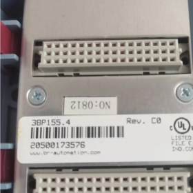
แบบอย่าง: 3BP155.4
Product Family: บี&ระบบอาร์ 2005 (Legacy 2005-series PCC, ล้าสมัย)
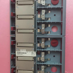
พิมพ์: 6-slot passive backplane / rack backplane
Variants Differentiation
✅ 3BP155.4: 6 สล็อต, without backup battery compartment
✅ 3BP155.41: 6 สล็อต, with backup battery mounting compartment (Battery part number: 0AC201.9)
Slot definition: Slot 1 is dedicated to power supply module (3PSxxx); the remaining 5 slots support CPU, I/O and communication modules.
- Key Electrical & ข้อมูลจำเพาะทางกล
| รายการ | พารามิเตอร์ |
| Number of slots | 6 Slots (1 PS slot + 5 module slots) |
| ขนาดโดยรวม | 240 มม (ว) × 165 มม (ชม) × 23 มม (ดี) |
| ระดับการป้องกัน | IP20 (สำหรับการติดตั้งตู้เท่านั้น) |
| อุณหภูมิในการทำงาน | 0 ℃~ +60 ℃ |
| อุณหภูมิในการจัดเก็บ | -25 ℃~ +70 ℃ |
| ความชื้นสัมพัทธ์ | 5~95%RH, ไม่ควบแน่น |
| การรับรอง | ซีอี, UL/cULus, อีเอซี, ยูเคซีเอ |
| การติดตั้ง | การติดตั้งราง DIN |
| วัสดุ | Metal shielded backplane + ที่อยู่อาศัยพลาสติก |
- ระบบ 2005 Full Range Backplane Comparison Table
| แบบอย่าง | Slot count | Battery compartment |
| 3BP150.4 / 3BP150.41 | 15 สล็อต | .41 version equipped |
| 3BP151.4 / 3BP151.41 | 12 สล็อต | .41 version equipped |
| 3BP152.4 / 3BP152.41 | 9 สล็อต | .41 version equipped |
| 3BP155.4 / 3BP155.41 | 6 สล็อต | .41 version equipped |
- Compatibility Instructions
- Supported modules: All System 2005 series modules (3PS power supplies, 3CP CPUs, 3DM/3DO/3AI/3AO I/O modules, 3EX communication modules)
- Incompatibility: Cannot intermix with X20 series modules (physical connectors and backplane bus are incompatible)
- Replacement solutions for obsolete unit
Maintenance spare parts: Source new surplus or used 3BP155.4 / 3BP155.41
New project upgrade: Full migration to B&ระบบ R X20 (No direct drop-in backplane replacement; hardware and program modification required)
- แนวทางการดำเนินงาน & On-site Pitfall Avoidance
- Reserve minimum 20 mm clearance on both ends of the DIN rail for heat dissipation;
- This is a passive backplane. Power supply is entirely provided by the power module installed in Slot 1;
- 3BP155.4 cannot be fitted with backup battery. If SRAM program/data retention during power loss is required, select 3BP155.41;
- Do not splice and extend backplanes of different series. ระบบ 2005 backplanes do not support multi-rack cascading;
- Always power off before removing modules to prevent damage to backplane connector pins.
- Typical Standard Configuration Example
Slot 1: 3PS465.9 (พาวเวอร์ซัพพลาย)
Slot 2: 3CP153.9 (ซีพียู)
Slot 3~6: อินพุต/โอดิจิทัล, อนาล็อก I/O, Profibus or CANopen communication modules
I can further provide upon request:
Backplane pinout definition;
Simple inspection procedure for second-hand units;
Complete migration plan from System 2005 to X20.
Complete Troubleshooting Procedure for B&R 3BP155.4 Passive Backplane
บันทึก: 3BP155.4 is a passive backplane without integrated chips or active circuits. It only contains PCB traces, backplane connectors and DIN rail grounding paths. Typical failures include bent/oxidized pins, broken copper traces, poor soldering, bad grounding and connector short circuits.
ความแตกต่างของโมเดล: 3BP155.4 (no battery housing) ≠ 3BP155.41 (with battery housing). Mechanically interchangeable, identical backplane circuit layout.
- อาการทั่วไปของความล้มเหลว (Distinguish backplane fault vs module fault)
Suspicious backplane failure symptoms
- Any module triggers error when inserted into a specific slot, while the same module works normally in other slots
- Multiple adjacent slots suffer simultaneous communication failures (broken backplane bus traces)
- Intermittent module drop-off, sporadic module recognition loss; fault reproducible when tapping/shaking the cabinet
- Power supply slot works normally, yet certain slots have no backplane bus power
- Frequent hot-swap alarms, communication CRC errors, PCC boot reporting missing modules
- Inserting a module into one slot causes power trip / ไฟฟ้าลัดวงจร (shorted backplane pins)
Faults NOT caused by backplane
Single module fails in every slot → defective module
No modules detected in all slots → Prioritize inspection of 3PS power supply and 3CP CPU
All hardware modules operate normally, only program errors occur → Software or parameter configuration issue
ขั้นตอน 1: การตรวจสอบด้วยสายตา (Power MUST be disconnected)
- Remove all modules and inspect spring contacts on every slot
งอ, tilted or bridged pins = short-circuit hazard, backplane condemned
Blackened, ออกซิไดซ์, corroded pins with verdigris → poor contact
- Inspect PCB rear side: Check for burn marks, cracks (No capacitors on passive backplane. Discard immediately if burnt traces are visible)
- Check grounding spring clip for DIN rail: Deformed or missing grounding clip leads to EMC interference and random communication faults
คำเตือน:Do not forcibly bend connector spring pins, which easily causes internal PCB trace fracture.
ขั้นตอน 2: Multimeter Continuity Test (Core Inspection Method)
Test Preconditions
Fully power down the unit and disconnect external power; remove all modules.
Set multimeter to continuity beep mode / โหมดต้านทาน.
ระบบ 2005 backplane bus consists of: Power rails (+5วี, จีเอ็นดี), parallel address bus, data bus and clock lines
Mandatory Test Items
- Common GND line
GND pins of all slots shall be mutually conductive;
GND shall conduct to backplane metal housing / DIN rail grounding clip.
✘ Abnormality: Disconnected GND for a slot → fractured PCB ground trace.
- Backplane +5V power rail
+5V pins of all slots shall be mutually conductive;
⚠ Critical warning: Continuity between +5V and GND = internal backplane short circuit. Backplane must be scrapped.
- Cross-slot continuity of bus signal lines
ระบบ 2005 adopts daisy-chain parallel backplane bus. Signal lines between adjacent slots shall conduct:
Slot 2 ↔ Slot 3 signal lines conductive
Slot 3 ↔ Slot 4 signal lines conductive
Slot 4 ↔ Slot 5 signal lines conductive
Slot 5 ↔ Slot 6 signal lines conductive
✘ Abnormality: Open circuit between adjacent slots → fractured internal PCB bus trace.
Quick Cross-test Method (On-site emergency diagnosis, no pinout required)
Module swap test (most commonly adopted by field automation engineers)
Operation steps:
- Keep power supply and CPU fixed in their slots;
- Insert a confirmed good I/O module sequentially into Slot 2,3,4,5,6;
- Power on and check if PCC recognizes the module:
Only one slot fails to detect module → damaged connector or traces for that slot
Slot2 works normally, Slot3 undetected, all slots after Slot3 fail → Bus trace broken between Slot2 and Slot3 (typical internal backplane damage)
ขั้นตอนที่ 3: Powered Functional Test (ข้อกำหนดเบื้องต้น: No visible short-circuit damage)
การกำหนดค่า: Slot1 with working 3PS power supply, Slot2 with working 3CP CPU, remaining slots empty.
- เปิดเครื่อง. If controller boots without hardware alarms → Main backplane power rail is basically intact
- Insert verified good modules one by one, check hardware diagnosis inside Automation Studio
Diagnostic message: Slotx Module missing / Bus error
Alarm persists for fixed slot, fault follows slot instead of module → Backplane failure confirmed
- Three Scenarios where repair is impossible – Direct replacement required
- Internal short circuit between +5V and GND (confirmed via multimeter continuity test)
- Cracked PCB substrate or broken internal bus traces (open circuit between cross-slot signal lines)
- Severely deformed spring contacts, bridged pins, melted connector plastic
- ความเข้าใจผิดที่พบบ่อย
- ❌ความเข้าใจผิด: “Passive backplanes cannot fail”. Rough module insertion, transportation vibration and long-term high temperature can fracture internal PCB traces or create bad solder joints.
- ❌ Mild oxidation cannot always be fixed by alcohol cleaning: Fatigued spring contacts tend to cause intermittent failures; replacement is recommended.
- ❌ Clarification: 3BP155.4 is only the backplane. Failure to boot CPU does not equal faulty backplane. Always check 3PS power supply and 3CP CPU first.
- Emergency Temporary Solution for Production Recovery
If only one slot has damaged traces:
Avoid using the faulty slot, rearrange modules to remaining functional slots for temporary operation.
Long-term solution: Replace 3BP155.4 spare part, or evaluate full migration to X20 platform.
Available supporting materials on request:
- Full pinout definition of 3BP155.4 slot connectors for precise multimeter measurement;
- Navigation path to view System2005 backplane bus faults in Automation Studio.





NH42-63-318x560.png "สวิตช์ถ่ายโอนอัตโนมัติชนิด CHINT PC (เอทีเอส)NH42-63/4SZ")



