 คอนแทคเตอร์,เบรกเกอร์,เซ็นเซอร์,ตัวเข้ารหัส,บมจ,ตัวแปลง


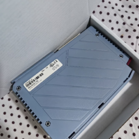
ข้อมูลพื้นฐาน
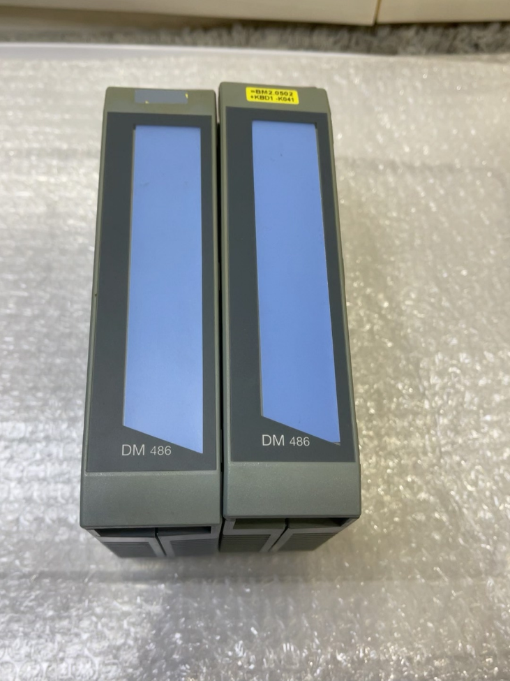
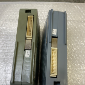
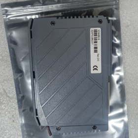
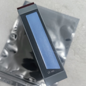
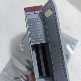
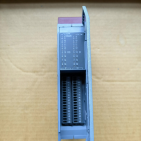
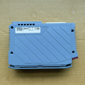
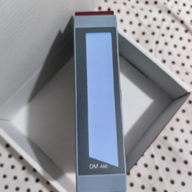
แบบอย่าง:3DM486.6
ยี่ห้อ: บี&อาร์ ออโตเมชั่น
Product Family: ระบบ 2005 (Legacy PCC Backplane System)
ประเภทโมดูล: ดิจิตอล Mixed I/O Module
⚠️ Status: Manufacturer Discontinued (ล้าสมัย). Only stock and second-hand spare parts available. New projects are recommended to migrate to the X20 series.
- Core Channel Specifications
| รายการ | พารามิเตอร์ |
| อินพุตดิจิตอล (จาก) | 16 ช่อง, 24 กระแสตรง, Sink/Source compatible (NPN/PNP universal) |
| Input Filter Time | 1 นางสาว |
| เอาท์พุทดิจิตอล (ทำ) | 16 ช่อง, Transistor Sourcing Output, 24 กระแสตรง |
| Per-channel Output Current | 0.5 ก / จุด |
| Maximum Total Module Output Current | 8 ก |
| การแยกไฟฟ้า | Galvanic isolation between input bank and output bank; no isolation between individual channels |
| การวินิจฉัย | Output short-circuit / overcurrent detection, per-channel LED status indication |
- ไฟฟ้า & ข้อมูลจำเพาะด้านสิ่งแวดล้อม
- การใช้พลังงาน
Backplane 5 วี: 1.2 ว
สนาม 24 วี ซัพพลาย: 2.2 ว
- คุณสมบัติการป้องกัน
Thermal shutdown upon output short-circuit, inductive load protection, external supply reverse polarity protection
- สภาพแวดล้อม
อุณหภูมิในการทำงาน: 0 ~ +60 องศาเซลเซียส
พื้นที่จัดเก็บ & อุณหภูมิการขนส่ง: -25 ~ +70 องศาเซลเซียส
ความชื้นสัมพัทธ์: 5%~95 %, ไม่ควบแน่น
ระดับการป้องกัน: IP20 (for cabinet mounting only)
- ข้อมูลจำเพาะทางกล
ระบบ 2005 single-width module
น้ำหนัก: ประมาณ. 0.32 กก
- Mandatory Terminals (Not included with module, สั่งซื้อแยกต่างหาก)
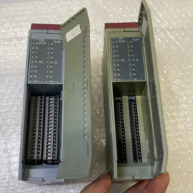
The module is equipped with sockets; terminal blocks must be ordered separately. 2 pcs of 18-pin terminals required
7TB718.9: แผงขั้วต่อสกรู, 1.5 มม.²
7TB718.91: Cage Clamp spring terminal block, 1.5 มม.²
X1 connector: DO1~DO16; X2 connector: DI1~DI16
- ความเข้ากันได้ของซอฟต์แวร์
Minimum supported Automation Studio version: V2.6
Corresponding hardware upgrade package required: V1.0.1.0
- ตัวเลือกการทดแทน (ข้อมูลสำคัญ)
1) Drop-in compatible within the same platform (Retain System2005 backplane & ซีพียู)
No direct pin-to-pin upgraded model. Similar reference within series:
3DM476.6: 16จาก + 16ทำ, supports DC/AC24 V inputs (different electrical characteristics for selection)
2) Platform Migration (โครงการใหม่ / complete cabinet retrofit, System2005 → X20)
Functionally equivalent combination:
X20DI9371 (16จาก) + X20DO9322 (16ทำ)
ข้อดี: Stable long-term availability, มีสต็อกเพียงพอ, enhanced diagnostic functions.
- การใช้งานทั่วไป
เครื่องจักรบรรจุภัณฑ์, อุปกรณ์สิ่งทอ, แท่นพิมพ์, legacy production line retrofits; used for signal acquisition from proximity switches and pushbuttons, and driving small loads such as solenoid valves and indicator lamps.
⚠️ คัดเลือก & Maintenance Precautions
- Output is Sourcing type (พีเอ็นพี). Connect load negative terminal to 0 วี; cannot be directly wired for sinking drive.
- Do not exceed 0.5 A continuous current per channel; total module output current must not exceed 8 ก.
- Freewheeling diodes must be wired in parallel for inductive loads (โซลินอยด์วาล์ว).
- System2005 backplane modules cannot be plugged directly into X20 bases; backplane bus protocols are incompatible.
- When purchasing discontinued spare parts, distinguish refurbished / ใช้แล้ว / brand-new surplus stock and confirm warranty terms.
หากจำเป็น, ฉันสามารถให้ได้:
1) Complete terminal pin assignment table
2) Standard DI/DO wiring schematic
3) Configuration key points for Automation Studio hardware setup
บี&R 3DM486.6 Hardware Installation Manual (Field Version)
Product Platform: บี&ระบบอาร์ 2005 PCC
ประเภทโมดูล: 16จาก / 16DO Digital Mixed I/O Module
สถานะ: Manufacturer discontinued, for spare part use only
ขอบเขต: Cabinet assembly, สายไฟ, power-on commissioning, การแก้ไขปัญหา
สารบัญ
- คำแนะนำด้านความปลอดภัย
- ผลิตภัณฑ์ & รายการอุปกรณ์เสริม
- การติดตั้งเครื่องกล (Backplane Mounting Procedure)
- Complete Terminal Pin Assignment
- ข้อมูลจำเพาะการเดินสายไฟฟ้า (DI/DO Schematic)
- ด้านสิ่งแวดล้อม & ขนาดการติดตั้ง
- Power-on Inspection & LED Indicator Definition
- Automation Studio Configuration Guidelines
- Operational Restrictions & ข้อผิดพลาดทั่วไป
- อัพเกรด & Replacement Guidance
- Mandatory Safety Instructions
- Module insertion / removal must be performed with power disconnected! Hot-plugging System2005 backplane modules is strictly prohibited; it may permanently damage backplane bus interfaces.
- Implement ESD protection before handling; wear anti-static wrist strap. Circuit boards are sensitive to electrostatic discharge.
- Fuses must be installed for external 24 แหล่งจ่ายไฟกระแสตรง; reverse polarity of power supply is forbidden.
- Freewheeling diodes must be fitted in parallel to inductive loads (โซลินอยด์วาล์ว, คอนแทคเตอร์) driven by output channels.
- Module protection rating IP20, installation inside control cabinet only. Do not expose directly to dust or moisture.
- Galvanic isolation exists between DI bank and DO bank; no channel-to-channel isolation. Separate low-level I/O cables from power cables during wiring.
- โมดูล & อุปกรณ์เสริมบังคับ
โมดูลหลัก
แบบอย่าง: 3DM486.6
ช่อง: 16×DI (24 VDC Sink/Source) + 16×DO (24 VDC Sourcing transistor output, 0.5 ต่อช่อง)
Terminals to be ordered separately (Not supplied with module)
7TB718.9: 18-pin screw terminal block, max conductor cross-section 1.5 มม.²
7TB718.91: 18-pin Cage Clamp spring terminal block, max conductor cross-section 1.5 มม.²
Quantity required: 2 เทอร์มินัลบล็อก (X1 for DO, X2 for DI)
- Mechanical Installation Steps for System2005 Backplane
- Confirm complete power-off of the entire PCC rack; isolate the power supply module from mains.
- Align the bottom guide slots of the module with the DIN rail backplane guides and slide horizontally into the slot.
- Press the side latches inward until an audible click confirms the module is locked to the backplane.
- Verify the rear gold-plated bus connector is fully seated against the backplane connector without tilting or gaps.
⚠️ Do not pry the module with screwdrivers. เพื่อถอดออก, release side latches and pull the module out parallel to the backplane.
- Vertically insert the 7TB718 terminal plugs into the lower X1 and X2 sockets of the module until fully engaged.
Mounting Clearance Requirements
Maintain minimum 25 mm ventilation space above and below each module;
อุณหภูมิแวดล้อมในการทำงาน 0 ℃~ +60 ℃. Implement cabinet temperature reduction if operating continuously above 55 ℃.
- Complete Terminal Pin Assignment
X1 = Output Terminal (DO1~DO16)
X2 = Input Terminal (DI1~DI16)
X1 (DO Output, 18 เข็มหมุด)
| เข็มหมุด | สัญญาณ | คำอธิบาย |
| 1 | DO1 | เอาท์พุทดิจิตอล 1 |
| 2 | DO2 | เอาท์พุทดิจิตอล 2 |
| 3 | DO3 | เอาท์พุทดิจิตอล 3 |
| 4 | DO4 | เอาท์พุทดิจิตอล 4 |
| 5 | DO5 | เอาท์พุทดิจิตอล 5 |
| 6 | DO6 | เอาท์พุทดิจิตอล 6 |
| 7 | DO7 | เอาท์พุทดิจิตอล 7 |
| 8 | DO8 | เอาท์พุทดิจิตอล 8 |
| 9 | DO9 | เอาท์พุทดิจิตอล 9 |
| 10 | DO10 | เอาท์พุทดิจิตอล 10 |
| 11 | DO11 | เอาท์พุทดิจิตอล 11 |
| 12 | DO12 | เอาท์พุทดิจิตอล 12 |
| 13 | DO13 | เอาท์พุทดิจิตอล 13 |
| 14 | DO14 | เอาท์พุทดิจิตอล 14 |
| 15 | DO15 | เอาท์พุทดิจิตอล 15 |
| 16 | DO16 | เอาท์พุทดิจิตอล 16 |
| 17 | +24V_OUT | Common positive supply for outputs (internally routed on module) |
| 18 | 0วี จีเอ็นดี | Common ground for outputs |
✅ Output Type: การจัดหา / PNP Output
When DO is activated, +24 V is present on DO pin. Connect one terminal of load to DO, the other terminal to 0 วี.
X2 (อินพุต DI, 18 เข็มหมุด)
| เข็มหมุด | สัญญาณ | คำอธิบาย |
| 1 | DI1 | อินพุตดิจิตอล 1 |
| 2 | DI2 | อินพุตดิจิตอล 2 |
| 3 | DI3 | อินพุตดิจิตอล 3 |
| 4 | DI4 | อินพุตดิจิตอล 4 |
| 5 | DI5 | อินพุตดิจิตอล 5 |
| 6 | DI6 | อินพุตดิจิตอล 6 |
| 7 | DI7 | อินพุตดิจิตอล 7 |
| 8 | DI8 | อินพุตดิจิตอล 8 |
| 9 | DI9 | อินพุตดิจิตอล 9 |
| 10 | DI10 | อินพุตดิจิตอล 10 |
| 11 | DI11 | อินพุตดิจิตอล 11 |
| 12 | DI12 | อินพุตดิจิตอล 12 |
| 13 | DI13 | อินพุตดิจิตอล 13 |
| 14 | DI14 | อินพุตดิจิตอล 14 |
| 15 | DI15 | อินพุตดิจิตอล 15 |
| 16 | DI16 | อินพุตดิจิตอล 16 |
| 17 | COM+24V | Common positive for inputs (used for NPN / Sinking sensors) |
| 18 | COM_0V | Common ground for inputs (used for PNP / Sourcing sensors) |
Two DI Wiring Configurations
- PNP Sensor (Sourcing Type)
Sensor positive → DI channel; Sensor negative → 0 วี; Connect module X2.18 to field 0 วี
- เซ็นเซอร์ NPN (Sinking Type)
Sensor positive connected to 24 วี; Sensor output → DI channel; Connect module X2.17 to field +24 วี
Input hardware filter: Fixed at 1 นางสาว, non-adjustable via software.
- พิกัดไฟฟ้า
Backplane 5 V power draw: 1.2 ว
สนาม 24 V power draw: 2.2 ว
Maximum continuous per-channel output: 0.5 A DC24 V
Global module output current limit: 8 ก; prolonged overload not permitted
การแยกตัว: Galvanic isolation between DI bank and DO bank; no isolation between individual channels
การป้องกัน: Thermal shutdown for output short-circuit, การป้องกันขั้วย้อนกลับ
- ขนาดโมดูล (มม)
ความกว้าง: 25 (System2005 single-width module)
ความสูง: 130
ความลึก: 86
น้ำหนัก: ประมาณ. 320 ก
- LED Indicator Definition
One LED assigned per channel on module front face:
DI LED ON: High level detected on corresponding input channel
DO LED ON: Output enabled in program and hardware output switched ON
Power status: Standby LEDs illuminated when backplane supply is normal; no LED response upon backplane communication failure.
- Automation Studio Hardware Configuration Guidelines
- Minimum supported AS version: V2.6 and above
- Hardware library selection: `3DM486.6` System 2005 DM module
- Address mapping: Follow rack slot sequence; slot numbering starts from CPU and extends backward
- Diagnostics support: Software readable faults for output short-circuit and overload
สำคัญ: Cannot be installed directly onto X20 backplane; bus protocols are incompatible!
- Fault Troubleshooting Matrix
| อาการผิดปกติ | Possible Root Cause | การดำเนินการแก้ไข |
| No LED illumination on module | Backplane power absent / Poor module seating / Damaged backplane | Re-seat module after full power-off; Inspect 3PS465/3PS476 power supply modules |
| DO LED ON, external load inactive | Missing external 24 วี ซัพพลาย, cable break, failed load | Measure voltage at X1.17/18; Inspect load wiring |
| Recurring short-circuit alarms on outputs | Shorted load, per-channel current exceeding 0.5 ก, missing freewheeling diode for inductive loads | Install freewheeling diodes; distribute load current; Inspect cables for insulation damage |
| Fluctuating DI signals | การรบกวนทางแม่เหล็กไฟฟ้า, insufficient filtering, excessively long cables | Route DI cables separately; add RC snubber circuits; check supply voltage ripple |
| Individual channel failure | Channel burned out due to overcurrent; ไม่สามารถซ่อมแซมได้ | Replace module |
- ชุดติดตั้งเพิ่มเติม & Replacement Guidance
Same Platform Compatibility (No CPU/Backplane Modification)
Similar model: 3DM476.6 (Supports AC24 V inputs; pin assignment differs, wiring modification required)
Platform Upgrade System2005 → X20 (แนะนำสำหรับโครงการใหม่)
Functionally equivalent combination:
X20DI9371 (16จาก) + X20DO9322 (16ทำ)
ข้อดี: Long-term production availability, stable spare part supply, enhanced diagnostic capability.
- Wiring Engineering Specifications
- Separate I/O signal cables from power cables, minimum separation distance ≥30 cm; use shielded cables if separation cannot be achieved.
- Install independent fuses for all 24 VDC circuits (3~5 A recommended rating).
- Implement single-point earthing inside control cabinet; reliably connect signal ground and protective earth.
- Recommended cable cross-section: 0.75~1.0 mm².





NH42-63-318x560.png "สวิตช์ถ่ายโอนอัตโนมัติชนิด CHINT PC (เอทีเอส)NH42-63/4SZ")



