 คอนแทคเตอร์,เบรกเกอร์,เซ็นเซอร์,ตัวเข้ารหัส,บมจ,ตัวแปลง

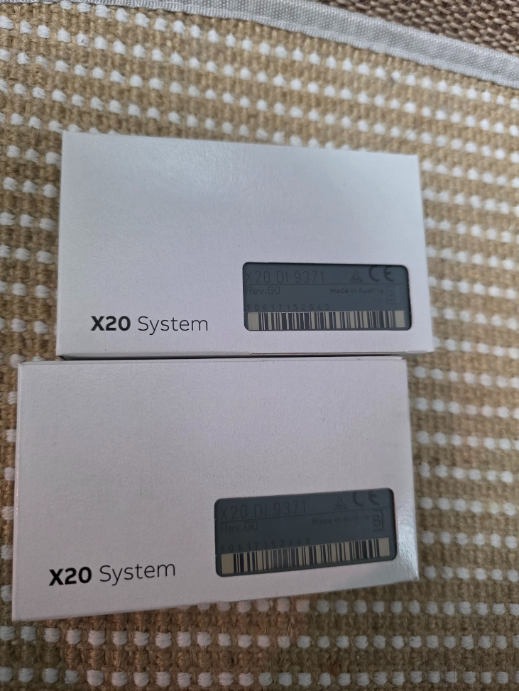

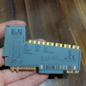
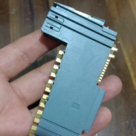
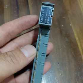
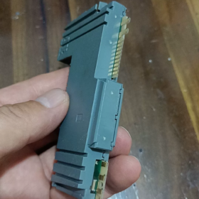
คำอธิบายรหัสรุ่น
X20DI9371
X20: X20 distributed I/O system platform
จาก: อินพุตดิจิตอล
9371: Module specification code
- Main Electrical & ข้อมูลจำเพาะของฮาร์ดแวร์
| รายการ | ข้อมูลจำเพาะ |
| จำนวนช่อง | 16 อินพุตดิจิตอล |
| ประเภทอินพุต | 24 VDC sinking / sourcing compatible, ไออีซี 61131-2 พิมพ์ 3 |
| แรงดันไฟฟ้าอินพุตที่กำหนด | 24 กระแสตรง (ช่วงการดำเนินงาน: 18~30 โวลท์ดีซี) |
| ความต้านทานอินพุต | ประมาณ. 3.9 kΩ |
| Logic ON (1) Threshold | ≥11 VDC |
| Logic OFF (0) Threshold | ≤5 VDC |
| Input Current per Channel | ≈6 mA @24 VDC |
| Response Delay | ทั่วไป 0.1 นางสาว; configurable hardware filter: 0.1 / 0.5 / 3 / 15 นางสาว (parameter setting via software) |
| วิธีการแยก | Group isolation: 4 ช่องทางต่อกลุ่ม, ทั้งหมด 4 isolated groups |
| Isolation voltage between groups: 500 VAC | |
| อินเตอร์เฟสบัส | X20 Link internal system bus |
| บ่งชี้สถานะ | Independent LED for each channel; module power LED |
| การใช้พลังงาน | Typ. 1.8 ว |
- เครื่องกล & ข้อมูลจำเพาะด้านสิ่งแวดล้อม
การติดตั้ง: มาตรฐาน 35 ราง DIN มม, การติดตั้งแนวนอน
ขนาด: ว 40 มม. × ส 100 มม. × ล 76.5 มม
อุณหภูมิในการทำงาน: -20 ℃ ~ +60 ℃ (inside control cabinet)
พื้นที่จัดเก็บ / อุณหภูมิการขนส่ง: -40 ℃ ~ +85 ℃
ระดับการป้องกัน: IP20 (สำหรับการติดตั้งตู้เท่านั้น)
การรับรอง: ซีอี, แอล 508, การรับรองทางทะเล GL, สอดคล้องกับ EN 61000 EMC industrial standards
- โครงสร้างภายใน & นิยามเทอร์มินัล
16 ช่องทางแบ่งออกเป็น 4 isolated groups:
Group1: CH0~CH3
Group2: CH4~CH7
Group3: CH8~CH11
Group4: CH12~CH15
⚠️ Important Wiring Rule: The common terminal of one isolated group must share the same 24 V polarity; Do NOT connect separate, non-referenced 24 V power supplies to different isolated groups, otherwise potential difference may damage the isolation circuit.
Wiring Configurations
- Sourcing Input (พีเอ็นพี เซนเซอร์)
Sensor output connects to module DI terminal; module common terminals connect to 0V(จีเอ็นดี)
- Sinking Input (NPN Sensor)
Sensor power terminal connects to 24V+, sensor output to DI terminal; module common terminals connect to +24V
- หลักการทำงาน
External digital sensor signal → Front-end RC hardware filter circuit → Optocoupler isolation group → Signal shaping circuit → X20 bus communication chip
The controller cyclically reads channel status via X2X/X20 CPU. Filter time parameters can be configured in Automation Studio to suppress contact bounce and interference pulses generated by inverters.
- ข้อมูลซอฟต์แวร์
ซอฟต์แวร์การเขียนโปรแกรม: Automation Studio 4.0 and all later versions supported
Hardware Identification: Standard X20 device description built-in library, no extra GSD file required
Process Image: Automatic channel address mapping; support signal forcing & online signal monitoring
Supported Functions: Channel diagnosis (no wire break detection, X20DI9371 does not support wire break diagnosis)
- การเปรียบเทียบแบบจำลอง & Compatible Replacement
Comparison with similar models in X20 series
| แบบอย่าง | ช่อง | คุณสมบัติการแยก | ลักษณะเฉพาะ |
| X20DI9371 | 16จาก | 4 channels per isolated group | Standard general-purpose module, ใช้กันอย่างแพร่หลายในโครงการ |
| X20DI9372 | 16จาก | Full channel individual galvanic isolation | For high-interference environments, multi-signals with different potentials |
| X20DI4371 | 4จาก | 4 channels per isolated group | Compact module for limited I/O points |
✅ Direct Replacement Conditions
If X20DI9371 is used in existing projects:
Upgrade for higher anti-interference performance: X20DI9372 (pin assignment compatible, no program modification required, wiring fully interchangeable; only difference is enhanced isolation performance)
❌ Not directly interchangeable: X20DI4371 has different channel quantity and terminal layout of base unit
- สถานการณ์การใช้งานทั่วไป
เครื่องมือกล, เครื่องจักรบรรจุภัณฑ์, material handling conveyors, ยาง & อุปกรณ์พลาสติก, การบำบัดน้ำ, general automation production lines
การรับสัญญาณ: Proximity switches, เซ็นเซอร์ตาแมว, ลิมิตสวิตช์, pushbuttons, หน้าสัมผัสรีเลย์แบบพาสซีฟ
- แนวทางการติดตั้ง & การแก้ไขปัญหา
Strict Prohibitions
- Never apply voltage higher than 30 กระแสตรง, will permanently damage input circuits
- Do not connect two non-common-ground 24 V power supplies to different isolated groups
- Avoid parallel routing of signal cables and power cables (strong electrical interference leads to flickering signals)
ข้อผิดพลาดทั่วไป
- Channel LED always ON: Signal wire short-circuited to ground; abnormal power supply for PNP sensor
- Signal intermittent fluctuation: Severe electromagnetic interference → increase hardware filter time; check shielding & การต่อสายดิน
- All channels in one group no signal: Loss of power supply to the corresponding group common terminal
- Compatible Base Units
Standard base: X20BM01 (screw terminal base)
Optional base: X20BM11 (spring-cage quick connect terminal)
Base must be ordered separately; terminal base is NOT included with the module!
X20DI9371 Terminal Pin Assignment
ฐานที่เข้ากันได้: X20BM01 (สกรู) / X20BM11 (ขั้วสปริง)
16 channels split into 4 galvanically isolated groups (4 channels each)
Group1: CH0~CH3|Group2: CH4~CH7|Group3: CH8~CH11|Group4: CH12~CH15
Terminal Sequence (Top to bottom on base)
Group 1 (CH0~CH3)
1: DI0
2: DI1
3: DI2
4: DI3
5: COM0 (Common terminal for Group1)
Group 2 (CH4~CH7)
6: DI4
7: DI5
8: DI6
9: DI7
10: คอม1 (Common terminal for Group2)
Group 3 (CH8~CH11)
11: DI8
12: DI9
13: DI10
14: DI11
15: คอม2 (Common terminal for Group3)
Group 4 (CH12~CH15)
16: DI12
17: DI13
18: DI14
19: DI15
20: COM3 (Common terminal for Group4)
Wiring Specifications Recap
- PNP Sensor (Sourcing Input, Industry Standard)
All COM0/COM1/COM2/COM3 → connect to 24 VDC 0V(จีเอ็นดี)
Sensor signal wire to DIx, sensor positive terminal to 24V+
- NPN Sensor (Sinking Input)
All COM0/COM1/COM2/COM3 → connect to +24 กระแสตรง
Sensor signal wire to DIx, sensor negative terminal to 0V
⚠️สำคัญ: COM0/COM1/COM2/COM3 are galvanically isolated from each other.
Do not connect different COM terminals to power supplies with non-shared ground potential!
Steps to Configure Input Filter in Automation Studio
- Locate X20DI9371 in project tree and double-click to open configuration window
- ชื่อพารามิเตอร์: Input filter time
Selectable options:
0.1 นางสาว (ตอบสนองอย่างรวดเร็ว, for high-speed signals)
0.5 นางสาว
3 นางสาว (recommended for normal pushbuttons & สวิตช์ความใกล้ชิด)
15 นางสาว (heavy interference environment, suppress contact bounce)
- Download project; parameters take effect immediately without power cycle



NH42-63-318x560.png "สวิตช์ถ่ายโอนอัตโนมัติชนิด CHINT PC (เอทีเอส)NH42-63/4SZ")



