 คอนแทคเตอร์,เบรกเกอร์,เซ็นเซอร์,ตัวเข้ารหัส,บมจ,ตัวแปลง

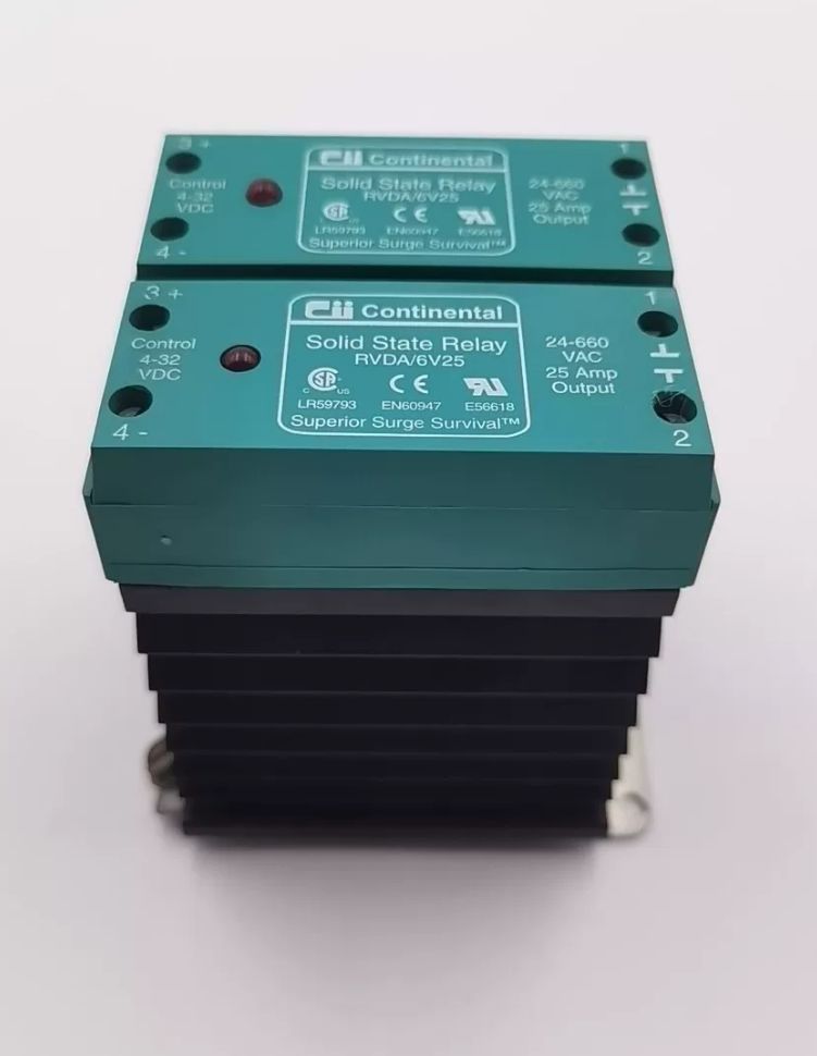

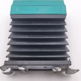
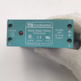
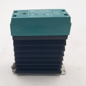
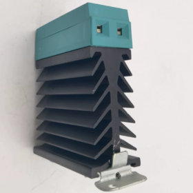
Original manufacturer Continental Industries(CII), later acquired by Invensys/Eurotherm; Model Obsolete. DIN-rail-mounted, DC-controlled AC single-phase zero-cross SSR。
Model Code Decomposition
| ส่วนรหัส | คำนิยาม |
| รถบ้าน | RV‑series SSR platform |
| ดี | DC control input; RVAA = AC input; RVMA = 4‑20 mA analog input |
| ก | Zero‑cross turn‑on |
| 6วี | Output AC voltage range: 24‑660 VAC; 3V = 24‑330 VAC |
| 25 | Rated resistive current 25 A(rms) @ 40 ℃ ambient temperature |
ข้อมูลจำเพาะทางไฟฟ้าที่สำคัญ
| รายการ | ค่า |
| DC Control Input | 4‑32 VDC; Min. 4 VDC / 3.5 mA, Max. 32 VDC / 8 mA |
| โหลดเอาท์พุต | 24‑660 VAC, 0.1‑25 A (ต้านทาน), 47‑63 Hz |
| การสลับโหมด | Zero‑cross turn‑on |
| Isolation Dielectric Strength | 4000 วี (Input‑to‑Output) |
| Off‑state Leakage Current | ≤ 10 mA @ 660 VAC |
| On‑state Voltage Drop | ≈ 1.0 VAC @ 25 A |
| Critical dV/dt | 1000 V/μs; SCR peak blocking voltage 1400 V |
| I²t Rating | 1350 A²·s |
| Holding Current | 100 มิลลิแอมป์ |
| เวลาเปลี่ยน | < 8.3 ms (60 เฮิรตซ์) |
| อุณหภูมิในการทำงาน | Full rating 0‑40 ℃; derating above 40 ℃, max. 80 ℃ |
| การติดตั้ง | DIN 35 rail / panel mount; heatsink mandatory |
หลักการทำงาน
Power SCR anti-parallel thyristor topology:
- 4-32 VDC applied to control input; internal current-limiting circuit drives thyristor gate.
- Zero-cross detection circuit: output is enabled only near AC voltage zero-crossing to reduce inrush stress.
- Upon removal of control signal, the device turns off naturally at AC current zero-crossing.
- Built-in RC snubber network suppresses voltage transients. 660 V high-voltage variant includes MOV surge absorber, no external bleeder resistor required.
การติดตั้งทางกายภาพ & สายไฟ
การติดตั้ง: Standard DIN 35 rail or screw-on panel mounting. Heatsink required for high power; forced air cooling for high-temperature service.
เทอร์มินัล: Input DC+, ดีซี-; Output Line, โหลด (AC non-polarized).
ข้อจำกัดที่ยาก: Never switch DC loads; ลดค่าโหลดอุปนัย; do not exceed 660 VAC; input voltage shall not exceed 32 VDC.
Obsolete-Model Replacement Options
Original part is manufacturer-discontinued. Two replacement scenarios:
- Pin-compatible functional drop-in alternatives
เทียบเท่าในประเทศ: Crydom DRA-DC-660D25; 4-32 อินพุต VDC, 660 VAC 25 A, DIN-rail zero-cross SSR.
European brand: Phoenix-Contact ELR 1-660DC-25.
- หมายเหตุสำคัญ: RVDA/6V25 is a 660 V high-AC-voltage SSR. Standard 480 V SSR cannot substitute directly; replacement output voltage rating ≥ 660 VAC is mandatory.
สถานการณ์การใช้งานทั่วไป
เครื่องทำความร้อนอุตสาหกรรม: resistive heaters, infrared lamps, time-proportion temperature-control cycling for resistance furnaces
Switching for fans and small AC-contactor coils (derate inductive loads to 12-15 A)
Ovens, เตาเผา, extruder temperature-control loops; PLC DC outputs driving high-voltage AC loads.
การหลีกเลี่ยงข้อผิดพลาดในการคัดเลือก
- Derate above 40 ℃; maximum usable current ≈ 12 A at 80 ℃; full-load operation prohibited.
- สำหรับโหลดอุปนัย (มอเตอร์, หม้อแปลงไฟฟ้า), limit actual load current to 12-15 A for a 25 A-rated SSR.
- Absolutely prohibited for DC-load switching.
- For 660 V systems, verify downstream insulation class. Up to 10 mA off-state leakage may cause faint glow on high-impedance loads.
Operating Principle of Solid-State Relay (สสส)
A Solid-State Relay (สสส) is a contact-less electronic switch. It has no armatures, metallic contacts or springs. Semiconductor devices (opto-coupler, เอสซีอาร์, TRIAC, MOSFET) perform low-level-to-high-power switching with galvanic isolation between input and output. SSR falls into AC-SSR and DC-SSR categories. The Continental RVDA/6V25 above is an AC zero-cross SSR.
Four-Block System Architecture
Control Input → Opto-Isolation → Trigger Logic Circuit → Power Semiconductor Switch → Load Output
- Input circuit: Receives low-level control signals (DC 4-32 V or AC 90-280 V) with current-limiting.
- Opto-coupler: Provides full galvanic isolation between control side and power side; typical isolation rating 2500-4000 V.
- Trigger-logic circuit: Main types: zero-cross trigger, random-phase trigger, phase-angle trigger, burst-fire trigger.
- Power-switch devices
AC-SSR: TRIAC or anti-parallel SCR pair (RVDA/6V25 uses anti-parallel SCR).
DC-SSR: Power MOSFET.
- AC-SSR (Zero-Cross Type exemplified by RVDA/6V25)
Turn-On Sequence
- Apply 4-32 VDC control signal; LED inside opto-coupler illuminates.
- Opto-coupler output activates; circuit monitors mains AC voltage.
- Zero-cross comparator waits for AC voltage within zero-cross window (±tens of Volts), then sends gate trigger pulses to SCRs.
- SCRs fire; AC load energized.
✅ Zero-cross advantage: Turn-on near zero voltage yields low inrush current and low EMI; ideal for resistive heating loads.
Turn-Off Behaviour
เอสซีอาร์ / TRIAC cannot turn-off instantly by removing control signal!
Remove input control → opto-coupler ceases trigger-pulse generation.
Thyristors remain latched-on. Turn-off occurs only when AC load current crosses zero and drops below holding-current threshold.
👉 For AC-SSR, after signal removal, load may remain powered for up to one-half mains cycle (20 ms @ 50 Hz).
Random-phase (non-zero-cross) สสส: Trigger immediately upon receiving control signal regardless of voltage phase, generating high EMI; used for phase-angle regulation.
Auxiliary Circuits
Internal RC snubber + MOV varistor: suppress voltage transients and protect thyristors from voltage spikes.
⚠️ The RC network introduces off-state leakage current: several mA up to ~10 mA. High-impedance loads may exhibit faint glow or flickering (RVDA/6V25 leakage ≤ 10 mA).
- DC-SSR (MOSFET-based)
Output stage uses power MOSFET for DC-load switching.
- Control signal active: opto-circuit drives MOSFET gate → MOSFET conducts → DC load powered.
- MOSFET turns-off immediately once control signal is removed; no zero-current requirement; switching in microseconds.
⚠️ Never use AC-SSR for DC-load switching: Once thyristors latch-on under DC, no natural current zero exists; device stays permanently shorted and suffers destructive failure.
SSR vs Electromechanical Relay (EMR)
| ลักษณะเฉพาะ | SSR Solid‑State Relay | EMR Electromechanical Relay |
| รายชื่อผู้ติดต่อ | Contact‑free semiconductor switching | Mechanical metal contacts |
| ตลอดชีวิต | Millions‑to‑hundreds‑of‑millions cycles; suitable for high‑frequency switching | Hundreds‑of‑thousands cycles; contact erosion under frequent operation |
| Acoustic Noise | Silent | Mechanical click on actuation / ปล่อย |
| Turn‑Off Behaviour | AC‑SSR waits for current zero‑crossing; off‑state leakage present | True galvanic contact‑gap; negligible leakage |
| Inductive‑load capability | ยากจน; heavy derating mandatory | Moderately good |
| Heat generation | แรงดันไฟฟ้าตกขณะอยู่ในสถานะ; heatsink required | Coil heating only; low contact drop |
Critical Practical Engineering Rules
- Resistive heating loads: select SSR rated current ≥ 1.2-1.5 × load nominal current.
- โหลดอุปนัย (หม้อแปลงไฟฟ้า, มอเตอร์, คอยล์คอนแทค): derate current by 50 %. ตัวอย่าง: 25 A SSR max. 12 A inductive load.
- Ambient-temperature rise requires current derating; high temperature drastically de-rates allowable output current.
- Heatsink installation is mandatory for high-power SSR; inadequate cooling destroys thyristors.
- Off-state leakage of AC-SSR makes it unsuitable for very low-power high-impedance loads.
Trigger-Logic Circuits for AC Solid-State Relays
Trigger-logic circuits reside between opto-coupler output and thyristor (TRIAC / anti-parallel-SCR) gate. การทำงาน: receive isolated control signal and generate gate trigger pulses according to predefined rules to fire AC power semiconductors.
DC-SSR (MOSFET output) has thyristor-free gate drive; trigger-logic circuits apply only for AC-SSR.
Four mainstream trigger schemes for AC-SSR:
- Zero-Cross Trigger — most common; used in Continental RVDA/6V25
- Random-Phase Trigger (Instant Non-Zero-Cross Trigger)
- Phase-Angle Trigger (Phase-Shift Regulation)
- Zero-Cross Burst-Fire Trigger (Cycle-Burst Power Regulation)
- Zero-Cross Trigger
Circuit Principle
Integrated AC-voltage zero-cross comparator.
When control input is active: trigger pulses are not generated immediately. Mains AC voltage is continuously sampled.
Gate pulses are output only inside zero-cross voltage window (typically ±10 V ~ ±50 V) to fire SCR/TRIAC.
Turn-off: Control signal removal stops new trigger pulses; thyristors commutate-off at AC-current zero-crossing.
Timing Characteristics
Turn-on constrained to voltage zero-cross region; maximum half-cycle delay @50 Hz (10 นางสาว).
✅ Pros: Low inrush current, minimal EMI; ideal for resistive heating and lamp loads.
❌ Cons: Only ON/OFF switching, no continuous voltage regulation. Response delay up to half mains cycle.
RVDA/6V25 uses zero-cross trigger with anti-parallel-SCR topology.
- Random-Phase Trigger (Instant Non-Zero-Cross)
Circuit Principle
No zero-cross detection. Trigger pulses are output immediately after isolated control signal arrives, regardless of instantaneous AC-voltage phase.
Timing Characteristics
Turn-on can occur at voltage peak; large inrush current and heavy electromagnetic interference.
Commutate-off still relies on AC-current zero-crossing.
✅ Pros: Fastest response; suited for fast-switching inductive loads.
❌ Cons: Severe EMI, mains pollution; not recommended for resistive heating; interferes with nearby instruments and sensors.
บันทึก: Random-phase trigger ≠ phase-angle regulation. It supports only full-ON / full-OFF; no power-level adjustment.
- Phase-Angle Trigger (Phase-Shift Regulation)
Circuit Principle
Requires external analog reference (0-10 วี / 4-20 มิลลิแอมป์). Synchronized to mains sine wave. Trigger pulse for each half-cycle is delayed by a controllable phase angle.
Conduction angle adjustable from 0° to 180°. Longer delay → shorter conduction interval → lower average output voltage.
Timing Characteristics
Controllable trigger instant for every half-cycle, achieving continuous voltage adjustment.
✅ Applications: Light dimming, transformer voltage regulation, continuous power control.
❌ Cons: Generates significant harmonics and EMI; long-term use for resistance furnaces is not recommended.
Analog-input SSR of RVMA series implement phase-angle trigger internally.
- Zero-Cross Burst-Fire Trigger (Cycle-Burst Power Regulation)
Circuit Principle
Switching unit = complete full-wave AC cycles.
Algorithm: N full-cycles ON, M full-cycles OFF; every turn-on / turn-off event occurs at voltage zero-crossing.
Average output power adjusted by modifying duty-cycle ratio: number-of-ON-cycles / total-cycles.
✅ Pros: All switching events at zero-cross; EMI far lower than phase-angle control; suited for high-power industrial resistance furnaces and extruder heaters.
❌ Cons: Discrete cycle-based power steps; power output pulsates at mains-cycle rate; unsuitable for loads sensitive to power fluctuation.
Distinction reminder:
Zero-cross ON/OFF: simple discrete switching.
Burst-fire: rapid periodic ON/OFF to modulate average power. Both perform zero-cross switching.
Comparison Table of Four Trigger Schemes
| Trigger Type | Trigger Condition | Output Characteristic | EMI Level | การใช้งานทั่วไป |
| Zero‑Cross Trigger | Fire only inside voltage zero‑cross window | ON/OFF only; no voltage regulation | ต่ำมาก | Resistive heating, infrared lamps (RVDA/6V25) |
| Random‑Phase Trigger | Fire immediately upon signal arrival, any phase angle | ON/OFF only; no voltage regulation | สูง | Fast‑switching inductive loads |
| Phase‑Angle Trigger | Controllable phase‑angle delay for each half‑cycle | Continuous voltage regulation | สูงมาก | Light dimming, transformer regulation |
| Burst‑Fire Trigger | Switch complete AC cycles at zero‑cross | Average‑power modulation by duty‑cycle | ต่ำ | High‑power industrial resistance furnaces |
Common Engineering Pitfalls
- Zero-cross SSR is non-instantaneous. Load energization may wait for up to half-cycle after control signal asserts; de-energization also has half-cycle maximum delay.
- Do not confuse random-phase trigger and phase-angle regulation: both can fire at voltage peak, but random-phase trigger supports only full-ON / full-OFF and cannot adjust power.
- For 4-20 mA analog-input SSR: Some variants implement phase-angle regulation, others implement burst-fire cycle-modulation. Always consult datasheet; they are not interchangeable.
เสริม: Two Gate-Drive Implementations
- Opto-TRIAC direct gate drive: Low-current SSR. Opto-coupler TRIAC directly drives output-stage TRIAC gate.
- Opto-coupler + amplifier-logic circuit (used by high-power anti-parallel-SCR SSR like RVDA/6V25): Opto-coupler transfers isolation-encoded signal only. Post-stage comparators, logic gates and pulse amplifiers supply sufficient gate-drive current for SCR firing



NH42-63-318x560.png "สวิตช์ถ่ายโอนอัตโนมัติชนิด CHINT PC (เอทีเอส)NH42-63/4SZ")



