 คอนแทคเตอร์,เบรกเกอร์,อินเวอร์เตอร์พลังงานแสงอาทิตย์,มิเตอร์ไฟฟ้า,แบตเตอรี่พลังงานแสงอาทิตย์


This solution customizes a dedicated control cabinet for the vibratory automatic nut/bolt conveyor (hereinafter referred to as the “vibratory feeder”), adapting to the core on-site industrial requirements such as single/multi-lane vibratory bowl feeding, production line interconnection, and automatic fault detection. It complies with national standards including GB 50055-2011 Code for Design of Electrical Distribution for General Electrical Equipment and GB 7251.1-2013 Low-voltage Assembled Switchgear and Controlgear, and balances operational convenience, operational stability and on-site adaptability. The cabinet is directly applicable to production, commissioning and on-site implementation.
- Core Design Principles and Application Scenarios
- Design Principles
Adaptability: Matches the core working conditions of the vibratory bowl including variable frequency speed regulation, start-stop control and material detection, and supports interconnection with production line PLCs/machine tools;
ความน่าเชื่อถือ: Selection of industrial-grade components, isolated design of high-voltage and low-voltage circuits, and protection against on-site dust and electromagnetic interference;
Operability: Dual modes of local manual operation and remote automatic operation, simple operation panel, and intuitive fault alarm;
Scalability: Pre-reserved interfaces to support future functions such as multi-lane expansion, feeding counting and remote monitoring.
- สถานการณ์การใช้งาน
Feeding of nuts/bolts via single/double-lane vibratory bowls (suitable for conventional fasteners of M3-M20);
Industrial sites such as automobile, hardware and assembly lines, which can operate independently or in conjunction with production line equipment;
Indoor normal temperature environment (-10℃~45℃), and industrial workshops with moderate dust/humidity (matching protection grade).
- Core Technical Parameters of the Control Cabinet
| รายการ | พารามิเตอร์ทางเทคนิค | หมายเหตุ |
| Rated Supply Voltage | Three-phase AC380V±10% 50Hz / Single-phase AC220V±10% | Selected based on the motor type of the vibratory bowl |
| Control Circuit Voltage | DC24V/2A | Power supply for photoelectric/proximity switches and indicator lights |
| Rated Output Power | 0.2kW~2.2kW per lane | Adapted to conventional vibratory bowl motors (single lane) |
| Control Mode | Local manual / Remote automatic | Knob switching with interlock protection |
| Speed Regulation Method | Variable frequency stepless speed regulation | Adjustable 0~50Hz for precise feeding speed control |
| Detection Signal | NPN/PNP photoelectric/proximity switch | Compatible with mainstream detection components |
| Interconnection Signal | Dry contact / 485 (Modbus-RTU) | Two-way communication with production line PLCs/machine tools |
| Cabinet Protection Grade | IP54 (มาตรฐาน) / IP65 (outdoor/high dust) | Sealed design with cold-rolled steel plate |
| สภาพแวดล้อมในการทำงาน | Temperature -10℃~45℃, Humidity ≤85% (ไม่มีการควบแน่น) | Conventional indoor industrial environment |
III. Core Configuration of the Electrical System (Standard for Single Lane)
Designed with separate circuits of “วงจรหลัก + control circuit + detection circuit + execution circuit”, the components are selected from industrial-grade brands including Schneider/Chint/Delixi (customizable according to user brand preference). The high-voltage circuits (AC380V/220V) and low-voltage circuits (ดีซี24วี) are completely isolated to avoid electromagnetic interference.
- Main Circuit Components (พาวเวอร์ซัพพลาย)
| Component Name | Reference Model (ชินท์) | การทำงาน |
| Molded Case Circuit Breaker | NM1-63S/3P 10A (สามเฟส) / DZ47-63 10A (single-phase) | Short circuit and overload protection for the main power supply, and main power cut-off |
| Variable Frequency Drive | NVF2-0.75/220V/380V | Stepless speed regulation and soft start for the vibratory bowl motor |
| Thermal Overload Relay | NR2-11.5 (ไม่จำเป็น) | Backup overload protection for the motor |
- Control Circuit Components (Signal and Logic)
| Component Name | Reference Model (ชินท์) | การทำงาน |
| Switching Power Supply | NED-30-24 (30W/24V/1.25A) | Power supply for detection components and indicator lights |
| Intermediate Relay | JZX-22F/2Z DC24V | Signal amplification and control circuit isolation |
| Changeover Switch | LW26-20 3-speed | Switching between manual/stop/automatic modes |
| Emergency Stop Button | NP4-11ZS/RED Normally Closed | Emergency power cut-off with mushroom head self-locking |
| Start/Stop Button | NP4-11BN/GN (สีเขียว) / NP4-11BN/RED (red) | Local manual start and stop |
- Detection and Feedback Components (Standard Interfaces, External Components)
| Component Type | Adapted Specification | การทำงาน |
| Diffuse Reflection Photoelectric Switch | NPN/PNP Normally Open DC24V, Detection Distance 50mm | Detection of material shortage/jamming in the feeding lane |
| Proximity Switch | NPN/PNP Normally Open DC24V (ไม่จำเป็น) | Detection of material in place (precision feeding) |
| Audible and Visual Alarm Light | LTE-1101J DC24V Red-Yellow-Green | Operation (สีเขียว) / Material Shortage (สีเหลือง) / Fault (red) |
- Execution Components (External, Terminals Reserved in the Control Cabinet)
Vibratory bowl body (including vibration motor and feeding lane);
Electromagnet of the vibratory bowl base (for electromagnetic vibratory bowls, adapted to variable frequency/voltage regulation control).
- Core Logic of the Electrical Control System (Single Lane)
Adopting the design of “variable frequency speed regulation + detection interconnection + mode interlock”, the local manual mode is for on-site commissioning, and the remote automatic mode is connected to the production line. The system automatically enters low-power standby when idle. The core logic is as follows:
- Mode Switching Interlock
When the changeover switch is turned to Stop: Both the main circuit and control circuit are powered off, and the equipment is locked;
When the changeover switch is turned to Manual: Remote interconnection signals are invalid, and the equipment is only controlled by the local start/stop buttons. The frequency of the variable frequency drive is adjusted manually (feeding speed);
When the changeover switch is turned to Automatic: Local start and stop are invalid. The equipment is started by the “feeding request” signal sent by the production line PLC/machine tool and stopped by the “feeding completion” signal. The variable frequency drive operates at the preset frequency (remotely adjustable).
- Core Operational Logic
Automatic Mode: Production line feeding request → Intermediate relay pull-in → Variable frequency drive start → Vibratory bowl operation for feeding → Material in place in the feeding lane (detected by photoelectric/proximity switch) → Feedback of “feeding completion” to the production line → Continuous feeding if the production line has a persistent request; yellow alarm for material shortage; red alarm and shutdown for material jamming/motor overload.
Manual Mode: Local start → Variable frequency drive start → Vibratory bowl operation; adjust the potentiometer of the variable frequency drive to change the feeding speed → Shutdown via local stop/emergency stop.
- Fault Protection Logic
If any of the following conditions is triggered, the control cabinet will immediately cut off the power supply of the main circuit, the red audible and visual alarm light will stay on, and the equipment cannot be started before the fault is reset:
- Overload of the vibratory bowl motor (overload protection of the variable frequency drive / actuation of the thermal overload relay);
- Material jamming in the feeding lane (no material movement detected by the photoelectric switch for ≥5s);
- Emergency stop button pressed (self-locking, requiring manual unscrewing for reset);
- Overvoltage/undervoltage of the main circuit voltage (built-in protection of the variable frequency drive).
- Definition of Interconnection Signals (Dry Contact, 485 Customizable)
To adapt to production line PLCs, the control cabinet is pre-equipped with standard dry contact interfaces (clearly marked terminal blocks) to support two-way signal transmission. The signal definitions are as follows:
Input Signals (Production Line → Control Cabinet): Feeding Request (เปิดตามปกติ), Emergency Stop Interconnection (ปกติปิด);
Output Signals (Control Cabinet → Production Line): Feeding Operation (เปิดตามปกติ), Material Shortage Alarm (เปิดตามปกติ), Fault Shutdown (เปิดตามปกติ).
- Cabinet and Internal Layout Design
- Cabinet Specifications (มาตรฐาน, Customizable on-site)
วัสดุ: Cold-rolled steel plate with door thickness of 2.0mm and cabinet thickness of 1.2mm, surface electrostatic spray coating (gray/blue, industrial standard);
ขนาด: Floor-standing 600mm(ว)×800mm(ชม)×300mm(ดี) (standard for single lane), wall-mounted 400mm(ว)×500mm(ชม)×200mm(ดี) (low power);
เครื่องประดับ: Standard equipped with door lock, observation window (on the door), top lifting ring (for floor-standing type), bottom wire inlet hole (with rubber protective ring), and internal wiring duct.
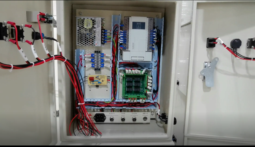
- Internal Layout (Isolation of High and Low Voltage Circuits, Easy Commissioning)
- Upper Part: Variable frequency drive and molded case circuit breaker (high-voltage of the main circuit, far from low-voltage components);
- Middle Part: Terminal blocks, intermediate relays and switching power supply (control/detection circuits, centralized wiring);
- Lower Part: Terminals and grounding bar (external connection of vibratory bowl/detection components, reliable grounding);
- Door Panel: Changeover switch, emergency stop button, start/stop button, audible and visual alarm light, and frequency adjustment knob of the variable frequency drive (centralized layout of the local operation area).
- ข้อมูลจำเพาะของสายไฟ
High-voltage (AC380V/220V): Copper core cables (BV2.5mm²/4mm²) are adopted, with red/yellow/green for phase lines, blue for neutral line, and yellow-green double color for ground wire;
Low-voltage (ดีซี24วี): Shielded cables (RVVP2×0.75mm²) are adopted to avoid electromagnetic interference, with single-end grounding of the shielding layer;
All circuits are routed through wiring ducts, the numbering of terminal blocks is consistent with the electrical schematic diagram, the circuits on the door panel are protected by corrugated pipes, and both ends of each wire are attached with permanent wire number labels.
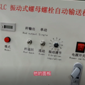
- Operation Panel Design (Door Panel, Simple and Intuitive)
The standard local operation panel is equipped with no redundant buttons, adapting to rapid operation in industrial sites. The layout from left to right/top to bottom is as follows:
- Mode Switching Knob: Manual → Stop → Automatic (3-speed with marks);
- Main Operation Area: Green start button (manual), red stop button (manual), and red mushroom head emergency stop button (centered and eye-catching);
- Status Feedback Area: Red-yellow-green audible and visual alarm light (top) and green operation indicator light of the variable frequency drive;
- Speed Regulation Area: Frequency adjustment knob of the variable frequency drive (0~50Hz with scale).
ปกเกล้าเจ้าอยู่หัว. Customized Expansion Functions (Optional According to User Requirements)
This solution is a standard configuration for single lane, and the following functions can be expanded according to on-site requirements. Interfaces and installation space are reserved in the control cabinet without the need for cabinet redesign:
- Multi-lane Control (Dual/Four Lanes)
Add variable frequency drives, intermediate relays and detection components; each lane has independent speed regulation and detection, supporting synchronous feeding/independent feeding;
Add a lane selection knob on the panel, and each lane is equipped with independent start/stop buttons and status indicator lights.
- Precision Counting and Quantitative Feeding
Add an electronic counter (DH48J) connected to the photoelectric switch of the feeding lane to realize “automatic stop after feeding N pieces”, with the counting value adjustable on the panel;
Support remote setting of counting threshold by the production line (485 การสื่อสาร).
- Remote Monitoring and Speed Regulation
Add a 485 โมดูลการสื่อสาร (Modbus-RTU) to support communication with production line PLCs/touch screens, and remotely read equipment status (operation/material shortage/fault) and adjust feeding speed;
Optional 7-inch touch screen (installed on the cabinet door) for local visual parameter setting and operation record viewing.
- Silo Level Interconnection
Add a silo level sensor (rotary resistance/ultrasonic) to detect the stock of nuts/bolts in the silo; issue a yellow alarm for low level and interlock with the feeding equipment (pre-reserved interface), and trigger shutdown protection for no material.
- Adaptation for Electromagnetic Vibratory Bowls
For electromagnetic vibratory bowls (non-motor type), replace the variable frequency drive with a voltage regulation controller to realize stepless adjustment of vibration amplitude, adapting to small and light fasteners (เช่น, M3-M6 nuts).
8. การติดตั้ง, Commissioning and Acceptance Standards
- On-site Installation Requirements
- Install the control cabinet in a vibration-free and dust-free area next to the vibratory bowl; fix the floor-standing type on the concrete ground with expansion bolts, and the wall-mounted type on a solid wall at a height of 1.2~1.5m for easy operation;
- Lay the power supply circuit independently, keep a distance from the on-site power line to avoid electromagnetic interference, and ensure reliable grounding (ความต้านทานต่อสายดิน ≤4Ω);
- When connecting external vibratory bowls and detection components, wire according to the marks on the terminal blocks, and adopt single-end grounding for the shielding layer of shielded cables (on the control cabinet side).
- Commissioning Steps (No-load → With Material → Interconnection)
- No-load Commissioning: เชื่อมต่อแหล่งจ่ายไฟ, switch to manual mode, start the equipment, adjust the frequency of the variable frequency drive, and check whether the vibratory bowl operates stably without abnormal noise or jamming, and whether the detection components and indicator lights work normally;
- Commissioning with Material: Add nuts/bolts, adjust the feeding speed (ความถี่), and check whether the feeding lane feeds smoothly, whether the material shortage/jamming detection is sensitive, and whether the alarm is accurate;
- Interconnection Commissioning: Switch to automatic mode, connect to the production line PLC, send feeding request/completion signals, and check whether the equipment is synchronized with the production line and whether the signal transmission is error-free;
- Fault Simulation: Simulate motor overload, material jamming and material shortage, check whether the equipment shuts down and alarms according to the logic, and whether it can start normally after fault reset.
- Acceptance Standards
- Electrical Performance: Insulation resistance of the main/control circuits ≥5MΩ (tested with 500V megohmmeter), no short circuit or electric leakage, and reliable grounding;
- Operational Performance: No abnormal noise during 30min no-load operation, smooth feeding during 2h operation with material without jamming/leakage, and precise detection and alarm;
- Interconnection Performance: 100 times of interconnection with the production line, no signal delay or packet loss, and synchronous actions;
- Protection Performance: Good cabinet sealing, compliance with IP54/IP65 protection grade, flexible panel operation and clear marks.
- After-sales Service and Maintenance Suggestions
- การบำรุงรักษารายวัน: Regularly clean dust on the cabinet surface, check whether the wiring terminals are loose, whether the lenses of detection components are clean (to avoid misjudgment), and whether the cooling fan of the variable frequency drive works normally;
- การบำรุงรักษาตามปกติ: Check the insulation resistance every 3 เดือน, fasten the wiring terminals every 6 เดือน, and replace aging wires and seals;
- Fault Troubleshooting: Attach a simple fault troubleshooting table in the control cabinet, marking the causes and solutions of common faults (such as failure to start, feeding jamming and false alarm) for quick on-site resolution.
- Design Output Documents (Customized Delivery)
To facilitate the production, on-site installation and subsequent maintenance of the control cabinet, the following complete set of technical documents (electronic + paper version) will be delivered after customization:
- Electrical schematic diagram (CAD + PDF version);
- Bill of components (including model, brand, quantity and specification);
- Cabinet layout drawing (internal/door panel);
- Terminal block wiring diagram (with numbering);
- Installation and commissioning manual (including steps and notes);
- Fault troubleshooting manual (including common faults and solutions).
Key Notes on Cabinet and Wiring of Control Cabinet for Vibratory Automatic Nut and Bolt Conveyor
Cabinet and wiring are the core of the control cabinet for vibration resistance, anti-interference, stable operation and convenient subsequent maintenance. Combined with the working condition characteristics of the vibratory feeder (on-site vibration, variable frequency speed regulation and numerous low-voltage detection signals), the design shall follow the principles of strict isolation of high and low voltage circuits, vibration resistance and anti-loosening, sealed protection and clear marking. The following are actionable modular notes applicable to on-site industrial operation requirements.
- Cabinet-related Notes
The cabinet shall balance structural strength, sealed protection, vibration-resistant fixation and internal area separation to adapt to the industrial site environment around the vibratory bowl (slight vibration, dust and multi-equipment interconnection). The design focuses on vibration and loosening prevention, dust prevention and physical separation of high and low voltage circuits.
- Cabinet Selection and Material
- วัสดุ: Prioritize cold-rolled steel plate with door thickness ≥2.0mm and cabinet side/back plate thickness ≥1.2mm to ensure structural strength and avoid cabinet deformation and internal component loosening caused by vibration; adopt electrostatic spray coating on the surface (anti-corrosion spray coating optional for outdoor/high dust environments) to prevent corrosion from on-site dust and water vapor.
- เกรดการป้องกัน: Select according to needs: IP54 (dust and splash proof) for conventional workshops, IP65 (completely dust proof and strong water jet proof) for high dust/outdoor open-air environments. The cabinet door gaps and wire inlet holes shall be equipped with sealing rubber strips/rings with no exposed gaps.
- Dimension Adaptation: Prioritize 600×800×300mm (floor-standing) / 400×500×200mm (wall-mounted) for single lane; expand the dimensions according to the number of components for multi-lane to ensure the spacing between internal components ≥50mm (for easy heat dissipation and commissioning), and reserve independent heat dissipation space for the variable frequency drive (≥100mm from other components).
- Installation and Fixation (Core Vibration Resistance Requirements)
- สถานที่ติดตั้ง: Keep away from the vibratory bowl body (high-frequency vibration during the operation of the vibratory bowl may cause loosening of cabinet terminals and wire harnesses) with a spacing ≥500mm; it is strictly forbidden to fix the cabinet on the vibratory bowl base or production line vibration frame, and fix it independently on the concrete ground/solid wall.
- Floor-standing Cabinet: Fix the bottom feet of the cabinet with 4 or more M10 expansion bolts (full circumference fixation without suspension); rubber shock absorption pads can be added to the feet to further buffer slight on-site vibration.
- Wall-mounted Cabinet: Install on concrete walls/steel structure columns with expansion bolts (forbid installation on light partition walls/iron sheet frames) at a height of 1.2~1.5m (for easy operation of the operation panel and observation of the alarm light) to avoid inconvenient maintenance caused by overhigh or overlower installation.
- Operation Space Reserved Around the Cabinet: ≥800mm on the front, ≥300mm on the sides/back for easy wiring, commissioning and subsequent inspection; keep away from high-temperature equipment (เช่น, welding machines, ovens) and water vapor sources (เช่น, cooling water tanks).
- Cabinet Structure and Accessory Details
- Wire Inlet/Outlet Holes: All equipped with rubber protective rings/plastic nozzles to avoid cable damage by metal edges; open holes according to the number of cables, and seal unused holes with sealing plugs to ensure the protection grade; prioritize wire inlet from the cabinet bottom (high-voltage) + side (low-voltage) to avoid water inflow from the top.
- Internal Layout: Pre-set physical separation of high-voltage area (upper part) + low-voltage area (middle part) + wiring area (lower part) separated by wiring ducts/partitions; place high-voltage components such as variable frequency drives and circuit breakers far from low-voltage components such as switching power supplies and terminal blocks to prevent electromagnetic interference.
- Standard Accessories: Add lifting rings on the top of floor-standing cabinets; install integrated wiring ducts (separate ducts for high and low voltage circuits) and independent copper grounding bars (≥2mm thick) inside; equip the door panel with observation windows (for viewing indicator lights) and waterproof door locks; reserve heat dissipation holes on the cabinet sides (with dust nets for IP54 and above).
- Operation Panel: Centralize all buttons, knobs and alarm lights without obstruction; place the emergency stop button in the center and higher than other buttons (eye-catching for emergency operation); place the speed regulation knob of the variable frequency drive close to the start/stop buttons to reduce operation movement.
- Other Protection Requirements
- Reliable Grounding of the Cabinet: Connect the cabinet shell to the internal grounding bar with a yellow-green double color wire, and lead the grounding bar to the on-site grounding electrode to ensure the cabinet is at the same potential as the ground and prevent electric leakage and electric shock.
- Outdoor/High Humidity Environment: Add dehumidification and anti-condensation devices (เช่น, small dehumidifiers, heating plates) inside the cabinet to avoid short circuit of switching power supplies and relays caused by condensation.
- Wiring-related Notes
Wiring is the key to the control cabinet for electromagnetic interference resistance, vibration resistance and anti-loosening, and stable signal transmission. The core principles are strict isolation of high and low voltage circuits, standardized use of shielded cables, anti-loosening of all contacts and permanent clear marking. The wiring shall adapt to the working conditions of the vibratory bowl including variable frequency speed regulation (prone to harmonic generation) and low-voltage detection (photoelectric/proximity switches with signals susceptible to interference). The specific requirements are as follows:
- หลักการ: Complete Physical Isolation of High and Low Voltage Circuits
This is the most critical requirement, which directly determines the stability of detection signals and whether false alarms/misjudgment of material jamming occur:
- Separate duct wiring and terminal block connection for high-voltage circuits (AC380V/220V, วงจรหลัก: variable frequency drives, เบรกเกอร์วงจร, motor wires) and low-voltage circuits (ดีซี24วี, control circuit: switching power supplies, detection components, รีเลย์). Mixed wiring in the same duct or terminal block is strictly forbidden, with a spacing ≥50mm.
- Route high-voltage cables through red/yellow/green wiring ducts and low-voltage cables through blue/white wiring ducts, and attach marks outside the ducts for quick distinction.
- Prioritize shielded cables (RVVP2×0.75mm²) for low-voltage detection signals (photoelectric/proximity switches) to avoid electromagnetic interference from variable frequency harmonics and other on-site equipment; adopt single-end grounding for the shielding layer (only connected to the grounding bar on the control cabinet side, not grounded on the on-site detection component side) to prevent new interference caused by circulating current formed in the shielding layer.
- Cable Selection and Wire Diameter Specifications
Select cable types and wire diameters according to circuit functions. It is strictly forbidden to use thin cables for high-power equipment, and the dedicated wire color for grounding is irreplaceable. The specific selection is as follows:
| ประเภทวงจร | Cable Type | Recommended Wire Diameter | Wire Color Requirements | หมายเหตุ |
| Three-phase Main Circuit | Copper core hard wire BV | 4mm² for 0.75~2.2kW | Yellow/Green/Red (phase lines), สีฟ้า (neutral line) | Cables from variable frequency drive to vibration motor |
| Single-phase Main Circuit | Copper core hard wire BV | 2.5mm² for 0.75~1.5kW | สีแดง (phase line), สีฟ้า (neutral line) | Power supply for single-phase vibratory bowls |
| วงจรควบคุม | Copper core flexible wire RV | 0.75~1mm² | ดำ/ขาว | Wiring for buttons and relays |
| Low-voltage Detection Circuit | Shielded cable RVVP | 2×0.75mm² | Black/Blue | Signal transmission for photoelectric/proximity switches |
| Grounding Circuit | Copper core hard wire BV | ≥2.5mm² | Yellow-green double color (exclusive) | Grounding for cabinet, components and grounding bar |
All cables are national standard pure copper core; avoid non-standard aluminum core cables (poor conductivity, easy heating and fracture after vibration).
Minimize the length of cables from the variable frequency drive to the vibration motor (≤5m). If long-distance wiring is required, increase the wire diameter by one grade and protect with metal hoses to reduce harmonic interference.
- Wiring Technology and Vibration Resistance & Anti-loosening (Adapted to On-site Vibration Working Conditions)
High-frequency vibration during the operation of the vibratory bowl may cause loosening of cable terminals and damage to wire harnesses due to bending. The wiring technology shall focus on anti-loosening, anti-bending and fixation treatment:
- Route all cables through flame-retardant wiring ducts without suspension or crossing; the filling rate of cables in the ducts ≤70% (for easy heat dissipation and future cable addition); fix the wiring ducts inside the cabinet with screws at a fixed point every 300mm to prevent falling off due to vibration.
- Protect the cables on the door panel (buttons, alarm lights) with plastic corrugated pipes without fail, and fix both ends of the corrugated pipes with clamps to avoid cable damage caused by bending when the door panel is opened and closed; the corrugated pipes are seamlessly connected with the wiring ducts with no exposed wire harnesses.
- Terminal Crimping: Crimp cold-pressed terminals (fork/needle type, adapted to terminal blocks) at the ends of all cables; direct wire stripping and connection to terminals is strictly forbidden; crimp the cold-pressed terminals firmly with a crimping tool without loosening, and protect large-diameter cables (4มม.²) with insulating sleeves.
- Wire Harness Fixation: Bundle the exposed wire harnesses inside the cabinet (เช่น, outlet of the variable frequency drive, inlet of the switching power supply) into bundles with nylon cable ties at a tie every 200mm, and fix the bundles on the cabinet bracket after bundling to avoid wire harness shaking and friction with components caused by vibration.
- Terminal Block Wiring: Connect only one cable to each terminal block contact (parallel connection of two or more cables is strictly forbidden); tighten the screws after wiring, and reinforce with lock nuts/spring washers to prevent terminal loosening caused by vibration; fix the terminal blocks on the cabinet at a fixed point every 500mm.
- ข้อมูลจำเพาะของสายดิน (Dual Requirements of Leakage Prevention and Anti-interference)
The reliability of the grounding system is directly related to equipment safety and the stability of detection signals, and shall follow the principles of single-point grounding, independent grounding and full connection:
- Set an independent copper grounding bar inside the cabinet; all grounding points (cabinet shell, grounding terminal of the switching power supply, grounding terminal of the variable frequency drive, shielding layer of shielded cables, shell of detection components) are directly connected to the grounding bar, and series connection is strictly forbidden (series connection will lead to excessive grounding resistance and superposition of interference signals).
- Lead the grounding bar to the on-site dedicated grounding electrode with a yellow-green double color wire, with grounding resistance ≤4Ω; it is strictly forbidden to connect the grounding bar to the on-site neutral line or equipment shell to avoid electric shock in case of electric leakage.
- Cabinet Shell Grounding: Connect the cabinet shell to the internal grounding bar with a yellow-green double color wire of ≥2.5mm², remove the spray coating at the connection point (to ensure good metal contact), and apply anti-rust paint after connection.
- Variable Frequency Drive Grounding: Connect the variable frequency drive to the grounding bar independently without sharing the grounding terminal with other components to reduce the interference of variable frequency harmonics on low-voltage components through the grounding circuit.
- Marking and Numbering (Core of Subsequent Maintenance)
All marks shall be permanent, clear and consistent with the drawings to avoid failure to quickly locate circuits during subsequent commissioning/fault troubleshooting. The requirements are as follows:
- Cable Marking: Attach permanent waterproof and oil-proof wire number labels to both ends of each cable, with the label number consistent with the electrical schematic diagram and terminal block number (เช่น, L1-XT1:1, DC24V-XT2:5). Attach the wire number labels 100mm away from the terminals to avoid obstruction by cable ties/wiring ducts.
- Terminal Block Marking: Attach paper/metal labels next to the terminal blocks, marking the function of the terminal blocks (เช่น, XT1-Main Circuit Terminal, XT2-Control Circuit Terminal, XT3-Detection Circuit Terminal). Each terminal is engraved with a permanent number.
- Cabinet Marking: Attach equipment name, power supply specification and grounding mark on the outside of the cabinet door panel, and attach cable function marks next to the wire inlet holes (เช่น, “Three-phase 380V Inlet”, “DC24V Detection Signal Inlet”).
- Wiring Duct/Component Marking: Attach “High-voltage Area” และ “Low-voltage Area” marks outside the wiring ducts, and attach component name + model labels next to components such as variable frequency drives, switching power supplies and relays, consistent with the bill of components.
- Insulation Test and Subsequent Inspection
- Insulation Resistance Test must be conducted after wiring: Test with a 500V megohmmeter, with insulation resistance of the main circuit (AC380V/220V) ≥5MΩ, insulation resistance of the control/low-voltage circuit (ดีซี24วี) ≥2MΩ, and no short circuit in the grounding circuit; power on only after passing the test.
- Key Points of Subsequent Inspection: Regularly check whether the wiring terminals are loose, whether the cable ties of wire harnesses fall off, whether the shielding layer of shielded cables is well grounded, and whether the rubber rings of wire inlet holes are damaged. Especially for control cabinets around vibratory bowls, fasten the terminal block screws at least once a month.
III. Special Notes for Additional Adaptation to Vibratory Feeders
- Variable Frequency Drive Heat Dissipation Wiring: Keep the air outlet of the variable frequency drive’s cooling fan unobstructed with no cable obstruction around, and align the cabinet’s heat dissipation holes with the variable frequency drive to avoid shutdown due to overheat protection of the variable frequency drive.
- Multi-lane Control Cabinet: Adopt independent wiring and independent terminal blocks for the high and low voltage circuits of each lane to avoid the impact of one lane’s fault on other lanes; separate the wiring ducts by lane number (เช่น, Lane 1, Lane 2).
- On-site Interconnection Wiring: Route the interconnection signals (dry contact/485) with the production line PLC through low-voltage shielded wiring ducts, and use twisted pair shielded cables (RVVSP2×0.75mm²) สำหรับ 485 communication cables with a spacing ≥100mm from high-voltage circuits to reduce signal delay/packet loss.
- Audible and Visual Alarm Light Wiring: Route the alarm light cables through the low-voltage circuit and set independent terminals for easy future replacement, avoiding false alarms caused by sharing terminals with detection signals.


")


")

NH42-63-318x560.png "สวิตช์ถ่ายโอนอัตโนมัติชนิด CHINT PC (เอทีเอส)NH42-63/4SZ")


