 คอนแทคเตอร์,เบรกเกอร์,เซ็นเซอร์,ตัวเข้ารหัส,บมจ,ตัวแปลง

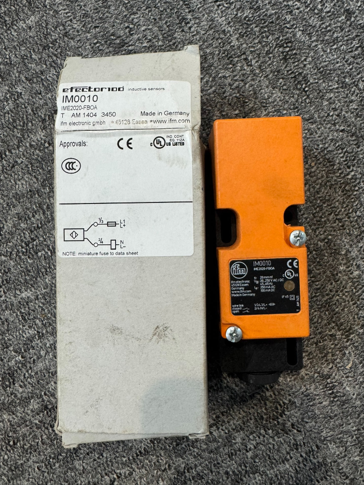

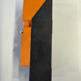
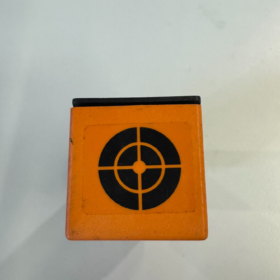
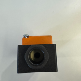
ข้อมูลพื้นฐาน
พิมพ์: Rectangular inductive เซ็นเซอร์ความใกล้ชิด (2-wire universal AC/DC)
ยี่ห้อ: ifm efector
การติดตั้ง: Non-flush (ไม่มีการป้องกัน)
Rated real sensing distance Sr: 20 มม
ขนาด: 40 × 40 × 121 มม
การเชื่อมต่อ: เคเบิลแกลนด์ M20×1.5, screw terminal block (สูงสุด. 2.5 สายเคเบิล มม.²)
ข้อมูลจำเพาะทางไฟฟ้าที่สำคัญ
แรงดันไฟฟ้าขณะทำงาน: 20…250 V AC/DC
เอาท์พุต: 2-ลวด, selectable normally open (เลขที่) / ปกติปิด (เอ็นซี)
การสลับความถี่: 20 เฮิรตซ์ (เครื่องปรับอากาศ) / 55 เฮิรตซ์ (ดี.ซี)
กระแสโหลดต่อเนื่อง
เครื่องปรับอากาศ: 250 มิลลิแอมป์ (ขึ้นไป 350 mA at ≤50 °C)
ดี.ซี: 100 มิลลิแอมป์
Minimum load current: 5 มิลลิแอมป์ (⚠️ Load current cannot be too low; otherwise the sensor fails to operate properly)
แรงดันไฟฟ้าตก: ≤6.5 V (เครื่องปรับอากาศ); ≤6 V (ดี.ซี)
กระแสไฟรั่ว: <2.5 มะ@ 250 VAC; <0.8 มะ@ 24 กระแสตรง
หมายเหตุสำคัญ: No reverse polarity protection, no short-circuit protection. A ≤2 A fast-acting fuse is recommended upstream.
ด้านสิ่งแวดล้อม & ข้อมูลทางกล
ระดับการป้องกัน: IP65
อุณหภูมิในการทำงาน: -25 ℃ … +80 ℃
วัสดุที่อยู่อาศัย: PPE engineering plastic
Status indicator: ไฟ LED สีเหลือง
Target material reduction factor: Steel=1|Stainless steel=0.7|Brass=0.4|Aluminum=0.3|Copper=0.2
การใช้งานทั่วไป
Metal object detection on conveyors, limit positioning for heavy machinery, metal stop plate identification in warehousing & โลจิสติกส์; ideal for sites with only AC220V power supply where DC24V is unavailable.
แนวทางการเดินสายไฟ
The 2-wire sensor must be wired in series with the load:
พาวเวอร์ แอล(+) → one sensor terminal → load → power N(-)
Do not short-circuit or energize without load; a minimum load of 5 mA is mandatory.
Comparison with Similar Models in the Series
| แบบอย่าง | ระยะการตรวจจับ | การติดตั้ง | โครงร่าง | ความแตกต่าง |
| IM0010 | 20 มม | Non-flush | 40×40×121 | Long housing, terminal connection |
| IM001A | 20 มม | Flush | 40×40×105 | Permitted for embedded metal mounting |
| IM0011 | 20 มม | Non-flush | Short housing, plug connection | รุ่นตัวเชื่อมต่อ |
Selection Risk Warnings
- 2-wire AC/DC sensors not recommended to directly drive DC PLC inputs. Leakage current may trigger false signals; 4-wire PNP/NPN types are preferred.
- Absence of short-circuit protection; cable damage in field environment can easily burn out the sensor.
- Minimum load current 5 มิลลิแอมป์; miniature relays and micro-indicator lamps may fail to draw sufficient operating current.
IFM IM0010 (IME2020-FBOA) Inductive Proximity Switch
Factors Affecting Sensing Distance (Nominal Sr = 20 มม)
The rated 20 mm is measured under standard test conditions: mild steel, standard-size target, reference mounting distance. Effective distance decreases under actual operating conditions.
- Target Metal Material (Dominant Influence)
Reference baseline: Mild steel St37 = 100% (20 มม)
Reduction factors:
สแตนเลส: ≈0.7 → Effective distance ≈14 mm
ทองเหลือง: ≈0.4 → ≈8 mm
อลูมิเนียม: ≈0.3 → ≈6 mm
ทองแดง: ≈0.2 → ≈4 mm
Intermittent detection of aluminum or copper workpieces commonly arises from severe reduction of effective sensing range.
- ขนาด & Thickness of Metal Target
IM0010 active sensing face: 40×40 mm
- Target dimensions smaller than active face → reduced sensing distance
- Steel plate thickness <1 mm prevents sufficient eddy current formation → distance attenuation
- Standard test target: 40×40×1 mm mild steel plate
- Sensor Mounting Layout (Critical for IM0010 – Non-flush Type)
IM0010 is an unshielded / non-flush sensor; NEVER install with metal tightly surrounding the housing.
- Metal brackets/housings adjacent to sensor sides and rear
→ Magnetic field is absorbed by metal, sensing distance reduced by 30%~60%, complete detection failure in severe cases
✅ Specification: Reserve ≥20 mm non-metallic clearance on all sides
- Multiple sensors mounted side-by-side
Mutual magnetic interference between adjacent unshielded inductive sensors causes false triggering and unstable detection range
✅ Minimum center-to-center spacing ≥3 × rated sensing distance ≈60 mm
- อุณหภูมิในการทำงาน
ช่วงการดำเนินงาน: -25 ℃~ +80 ℃
At high temperature (>60 ℃): Rising coil impedance weakens magnetic field and slightly reduces sensing distance
Low temperature generally imposes minor impact; sharp temperature fluctuations lead to switching point drift
- Supply Voltage Variation
IM0010 supply range: 20~250 โวลต์ เอซี/ดีซี
Low supply voltage weakens coil excitation magnetic field and slightly shortens effective sensing distance.
Avoid continuous operation near the lower limit of 20 วี.
- Target Approach Angle & Parallelism
- Tilted metal plate entering sensing zone reduces effective detection distance
- Diagonal approach achieves shorter trigger distance compared to perpendicular head-on approach
Optimal condition: Target plate parallel and perpendicular towards the sensing face.
- External Electromagnetic Interference
Close parallel routing with cables for inverters, contactors and high-power motors:
Alternating magnetic field disturbs the sensor oscillator circuit, presenting symptoms including:
Unstable detection range
No trigger at long distance, occasional loss of signal at short range
การปรับปรุง: Separate sensor wiring from power cables.
- Mechanical Contamination & Medium Conditions (IP65 rated)
- Ferrous dust/metal debris accumulated on sensing face acts as a premature metal target, causing advance triggering and sensitivity drift
- Water and oil contamination do NOT directly attenuate magnetic field (inductive sensors are unaffected by non-metallic media). อย่างไรก็ตาม, oil sludge mixed with iron powder creates interference.
- ความเข้าใจผิดที่พบบ่อย
✅ Non-metallic materials (พลาสติก, ยาง, timber, น้ำ) do not affect sensing distance
❌ Many mistakenly believe oil contamination reduces range; pure oil creates no impact. Interference only occurs with mixed iron dust.
On-site Practical Recommendations Specific to IM0010
- For stainless steel, aluminum targets, design installation clearance with sufficient safety margin (60%~70% of nominal sensing distance).
- As an unshielded sensor, metal brackets cannot fit tightly alongside the housing; proper clearance is mandatory.
- ระหว่างการว่าจ้าง, measure actual trigger distance using real workpieces on site. Do not directly adopt the nominal 20 mm for mechanical layout.
General Installation Specifications for Unshielded (Non-flush) Inductive Proximity Sensors
รุ่นที่ใช้งานได้: IFM IM0010, IM0011, IM001A and other rectangular unshielded inductive proximity sensors
หลักการสำคัญ: Unshielded sensors have no metal shielding around the coil. Magnetic field radiates outward in all directions. Surrounding metal absorbs magnetic flux, shortening detection distance, causing false operation or complete failure.
- Minimum Clearance for Single Sensor Installation (Highest Priority)
Let Sr = rated sensing distance (Sr = 20 mm for IM0010)
- Front of sensing face: Reserved for target metal, this rule does not apply
- Metal adjacent to sensor sides (left/right/top/bottom): Minimum clearance ≥ 1 × Sr
- Metal behind sensor rear end: Minimum clearance ≥ 2 × Sr
👉 Practical values for IM0010:
Side clearance to metal ≥20 mm; rear clearance to metal ≥40 mm.
⚠️ Forbidden: Clamping the sensor inside metal slots or tight metal cutouts!
If fixation is required, use plastic brackets or non-metallic spacers for isolation.
Installation Cutout Prohibition
Unshielded sensors must NOT be embedded into metal panel cutouts. Embedding wraps the sensor with metal and short-circuits the magnetic field.
Only shielded (flush mount) sensors allow embedded metal installation.
- Side-by-Side / Opposite Mounting of Multiple Unshielded Sensors (Prevent Mutual Magnetic Interference)
- Side-by-side parallel installation (all sensing faces facing same direction)
Minimum center-to-center distance ≥ 3 × Sr
IM0010: ≥60 mm
- Opposite mounting (two sensing faces facing each other)
Minimum separation ≥ 4 × Sr
IM0010: ≥80 mm
- Staggered perpendicular layout
Minimum spacing ≥ 2 × Sr
Consequences of insufficient spacing: Fluctuating detection range, random false triggering, detection only possible at close range.
- Specifications for Metal Targets
- เป้าหมายมาตรฐาน: Side length ≥ Sr, thickness ≥1 mm (mild steel)
- Target smaller than sensing face → reduced effective range
- Thin plates, thin stainless steel and aluminum parts require extra safety margin
- Target should ideally approach parallel and perpendicular to sensing face; angled entry reduces trigger distance.
- การเดินสาย & ข้อมูลจำเพาะของสายไฟ
- Avoid routing sensor cables closely alongside high-current power cables (อินเวอร์เตอร์, motor power lines). Maintain ≥30 cm separation; cross cables preferably at 90°.
- Prevent cables from prolonged high temperature, extrusion and abrasion.
- Do not wrap sensor cables around metal supports or hydraulic pipes.
- ด้านสิ่งแวดล้อม & Mechanical Precautions
- Regularly clean ferrous powder accumulated on sensing face to avoid false signals
- Secure mounting under vibration conditions to prevent sensor displacement and trigger offset
- For IP65/IP67 sensors, water and oil on sensing face impose no negative impact (non-metallic media do not attenuate magnetic field).
- Shielded vs Unshielded Sensor Comparison (การอ้างอิงการเลือก)
| รายการ | Shielded (ฟลัชเมาท์) | ไม่มีการป้องกัน (Non-flush, เช่น. IM0010) |
| Permitted embedded metal panel mounting | ✅ Allowed | ❌ต้องห้าม |
| Allowing tight contact with side metal | ✅ Permitted | ❌ Clearance required |
| Maximum sensing distance within identical housing size | Smaller | ใหญ่กว่า (main advantage) |
| Sensitivity to interference | ต่ำ | สูง; strict installation clearance required |
- Standard Field Commissioning Procedure
- Install per minimum clearance requirements; remove redundant surrounding metal
- Measure actual trigger distance with real on-site workpieces, instead of relying on datasheet nominal Sr
- Set mechanical operating distance ≤70% of measured actual distance to reserve safety margin
- Observe yellow LED indicator during target movement to confirm no intermittent signal loss.
- Common Faults Originated from Improper Installation
- Detection only possible at short distance: Metal too close to sensor sides/rear
- Intermittent random false triggering: Insufficient spacing between adjacent sensors causing magnetic interference
- No detection signal at all: Sensor fully enclosed by metal leading to magnetic field short circuit





NH42-63-318x560.png "สวิตช์ถ่ายโอนอัตโนมัติชนิด CHINT PC (เอทีเอส)NH42-63/4SZ")



