 คอนแทคเตอร์,เบรกเกอร์,เซ็นเซอร์,ตัวเข้ารหัส,บมจ,ตัวแปลง

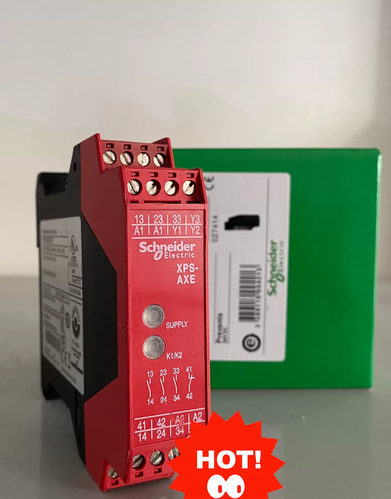

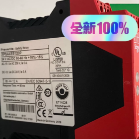
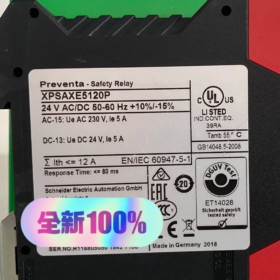
This model belongs to Schneider-Electric เทเลเมคานิก, NOT ร็อคเวลล์-เอบี. Many suppliers mislabel its brand.
วงจรชีวิตผลิตภัณฑ์: Discontinued on 2023-07-31; end-of-service on 2025-12-31, no original-factory supply available.
รายละเอียดรหัสรุ่น
| ส่วนรหัส | คำอธิบาย |
| XPS | Preventa safety module series |
| AXE | ซีรีส์ย่อย: basic module for E‑stop / การตรวจสอบสวิตช์ความปลอดภัย |
| 5120 | การกำหนดค่าฮาร์ดแวร์: 3 safety normally‑open outputs + 1 signal relay output, 24 V AC/DC power supply |
| ป | ประเภทเทอร์มินัล: screw‑clamp terminals (C = spring‑cage terminals) |
แกนไฟฟ้า & ข้อมูลจำเพาะด้านความปลอดภัย
| รายการ | พารามิเตอร์ |
| แรงดันไฟฟ้า | 24 วี เอซี/ดีซี (20.4‑26.4V) |
| ผลลัพธ์ด้านความปลอดภัย | 3 × Normally‑open (13−14, 23‑24, 33‑34), max.1.5A @24VDC |
| สัญญาณเอาท์พุต | 1‑channel relay signal output (for PLC) |
| ระดับความปลอดภัย | พีแอล อี / Category 4 (ISO 13849‑1); SIL CL 3 (IEC 62061) |
| การติดตั้ง | DIN‑rail mounting; ขั้วต่อสกรู; IP20 device body, IP40 inside cabinet |
| อุณหภูมิในการทำงาน | -25℃~+55℃; พื้นที่จัดเก็บ:‑25℃~+75℃ |
| น้ำหนัก | 0.4 กก |
| การรับรอง | แอล, ซีเอสเอ, BG approved |
หลักการทำงาน
Designed for dual-channel E-stop and safety-gate switch monitoring:
- S11-S12 and S21-S22 terminals connect to normally-closed contacts of E-stop / safety-gate switches for dual-channel redundancy detection.
- S33-S34 reset terminals: configurable for manual reset (with push-button) or auto-reset (ลัดวงจร).
- Mismatched status between two input channels triggers fault detection; outputs latch OFF and power-cycle reset is mandatory.
- Three safety normally-open outputs cut off hazardous circuits; one relay output provides diagnostic feedback to PLC
Main Terminal Definition
| เทอร์มินัล | การทำงาน |
| A1/A2 | 24 V AC/DC power supply input |
| S11‑S12 | Safety input Channel 1 (E‑stop / safety‑gate NC contact) |
| S21‑S22 | Safety input Channel 2 (E‑stop / safety‑gate NC contact) |
| S33‑S34 | Reset loop terminals |
| 13‑14 /23‑24 /33‑34 | 3 safety normally‑open outputs |
| Y74‑Y84 | PLC signal feedback relay output |
OEM-Recommended Replacement Model
Direct upgrade for XPSAXE5120P: XPSBAC1411P (Harmony XPSBAC series, 24VAC/ดีซี, ขั้วต่อสกรู. Full compatibility in functions and safety ratings; nearly identical terminal layout for direct DIN-rail replacement).
⚠️Replacement Notes:
- Verify reset logic; reset wiring logic remains identical between old and new models.
- Output contact ratings are unchanged; no modification to external contactors is required.
- XPSAXE5120P is legacy Preventa hardware; XPSBAC is new-generation hardware with slightly different LED indicator layout.
Application Scenarios of XPSAXE5120P
This dual-channel safety monitoring module achieves PL e / Cat.4 and SIL3. It features dual-channel E-stop & safety-gate monitoring, คู่มือ / auto-reset options, 3 safety relay outputs plus 1 feedback output. It is deployed for machinery safety-loop cut-off and shall be installed inside control cabinets only (IP20).
✅Qualified Application Scenarios
- Machine-Tool Industry
เครื่องกลึงซีเอ็นซี & ศูนย์เครื่องจักรกล: dual-channel E-stop push-button monitoring, emergency-stop safety loops; safety-gate closure detection for machine-tool protective doors, power-circuit cut-off upon door opening.
การบด & เครื่องกัด: Cut-off for main-contactor and servo power loops; Y74-Y84 feedback signals sent to PLC for fault alarming.
- บรรจุภัณฑ์ & โลจิสติกส์อัตโนมัติ
เครื่องบรรจุภัณฑ์, เครื่องปิดผนึกกรณี, palletizers and conveyor lines: monitoring for safety guard doors & perimeter safety gates; E-stop loops for equipment.
Assembly-line workstations: มอเตอร์ & pneumatic power cut-off when guard doors open to prevent personnel hazards.
- ยาง & Plastics Processing Equipment
Injection-molding & extrusion machines: mold safety-gate and equipment E-stop monitoring.
บันทึก: This safety relay implements only logic cut-off. Safety contactors must be deployed downstream for high-current loads; direct driving of high-power motors is prohibited.
- General-purpose Automated Production Lines & Robot-cell Perimeter Safety
Perimeter safety-gates and external E-stops for robot workcells.
บันทึก: Not a safety-light-curtain controller. It only processes contact-type devices (E-หยุด, safety switches) and cannot directly accept PNP/NPN OSSD signals from safety light curtains.
- แฟนๆ, Special-purpose Test Benches
E-stop and safety-gate monitoring for test benches. Complies with CE Machinery Safety standard EN ISO 13849 for export-oriented equipment certification.
📋Wiring Guidelines for Application
- S11-S12 / S21-S22: connect dual-channel normally-closed E-stop / safety-gate switches. Single-channel wiring downgrades safety rating; แมว.4 / PL-e compliance cannot be achieved.
- S33-S34: reset terminals. Manual reset with push-button; auto-reset by short-circuiting S33-S34.
- 13-14/23-24/33-34: three safety normally-open outputs, wired in series with contactor-coil loops for hazardous-energy cut-off.
- Y74-Y84: feedback output wired to PLC for HMI alarming and fault logging.
❌Disqualified Scenarios (ข้อผิดพลาดในการคัดเลือก)
- Cannot directly interface with safety light curtains (no OSSD input; select XPS-AC series dedicated light-curtain modules).
- ❌Not for high-frequency switching: this safety relay is a protective device actuated only during emergency / fault conditions, not for frequent load switching.
- ❌No direct driving of high-power motors; สูงสุด. contact rating 1.5A@24VDC. Safety contactors shall be connected downstream for heavy loads.
- ❌Cabinet-mount only (IP20). Forbidden for environments with condensation, heavy dust or corrosive gas.
- ❌Not suitable for explosive-hazardous locations.
Replacement-model Application Notes
XPSAXE5120P is obsolete. Replacement XPSBAC1411P shares identical applicable scenarios. No process-logic modification is required; only terminal wiring verification is needed.
Operating Principle of XPSAXE5120P
This is a dual-channel safety-monitoring safety relay, designed to satisfy ISO13849-1 Cat.4 / PL-e and SIL CL3. It monitors dual-channel normally-closed contact-based devices (ปุ่ม E-stop, safety-gate switches). Safety cut-off is implemented via dual-channel comparison verification, fault latching and reset logic.
- Internal Hardware Logic
- Power-supply loop: A1/A2 receives 24V AC/DC supply for module power-on self-test.
- Two fully independent safety input channels S11-S12 (Channel 1) and S21-S22 (Channel 2), physically isolated for dual-channel redundancy.
- Internal dual-channel detection circuit continuously compares status of the two input contacts.
- Safety-output relays: 3 groups of safety normally-open contacts (13-14, 23-24, 33-34) for hazardous-circuit cut-off.
- Auxiliary feedback relay Y74-Y84 transmits module status signals to PLC.
- Reset loop S33-S34: handles reset logic; outputs latch OFF upon fault until valid reset is performed.
⚠️Critical feature: internal fault-latching mechanism. Once hazardous status or channel mismatch is detected, safety outputs stay permanently OFF and will not auto-recover.
- Normal Operating Sequence
- เปิดเครื่อง: A1/A2 energized, module executes self-diagnosis.
- Safe condition (no safety-device actuation)
E-stop released / safety-gate closed: both S11-S12 and S21-S22 input channels are conducting (normally-closed contacts closed).
Identical dual-channel status confirms safe condition.
✅Internal safety relays pull-in; ผู้ติดต่อ 13-14, 23-24, 33-34 close to energize downstream contactor coils. Y74-Y84 auxiliary output closes to inform PLC of safe-ready status.
- E-stop triggered / safety-gate opened
E-stop pressed or safety-gate opened, both input channels open simultaneously.
The module detects safety-signal loss and immediately opens all three safety outputs, de-energizing downstream contactor-coil loops and stopping machine power.
Y74-Y84 feedback toggles accordingly; PLC receives fault signal and HMI triggers E-stop / gate-open alarm.
✔Module enters latched-fault state. Outputs will NOT auto-recover even after releasing E-stop or closing safety-gate.
- รีเซ็ตการทำงาน
รีเซ็ตด้วยตนเอง: push-button wired to S33-S34. After E-stop reset and gate closure, press reset push-button to release latch and restore safety outputs for machine enable.
Auto-reset: short-circuit S33-S34. Safety outputs unlock automatically once safe conditions are restored.
Safety-code recommendation: manual reset is strongly preferred for E-stop loops. Auto-reset carries unexpected-start risk.
- Dual-channel Fault-Detection Principle (Core Safety Mechanism)
This is the key to achieving Cat.4 / PL-e.
When two input channels report inconsistent status (เช่น. one contact of dual-channel E-stop sticks closed while the other opens), the module identifies external / internal fault.
All safety outputs open and latch permanently. Outputs cannot recover merely by restoring external-switch contacts.
A full power-cycle (disconnect A1/A2 supply) is required to clear the latch. Troubleshoot and replace defective E-stop / safety-gate switches before power-on and reset.
This logic detects contact welding and wire-break faults to prevent safety-function loss caused by single-component failure.
- Output-loop Logic
- Three safety outputs (13-14/23-24/33-34): safety-relay contacts
Wired in series with safety-contactor-coil loops as safety-cut-off paths. Not for direct high-power-load driving. สูงสุด. คะแนนการติดต่อ:1.5เอ @24VDC. All three contacts act synchronously internally.
- Y74-Y84 signal-feedback output
Auxiliary diagnostic relay, NOT a safety-related output. Used only for PLC status acquisition and fault alarming; must not be used for machine safety cut-off.
- Typical Fault-response Behaviours
- Single-channel wire-break or single-contact welding → channel mismatch → outputs open & latch; power-cycle troubleshooting required.
- Reset-loop open-circuit → reset denied; machine cannot start.
- Supply-voltage out-of-range → safety outputs force-open.
- Critical Boundary Constraints
- Only normally-closed dual-channel devices are acceptable. Safety-light-curtain OSSD signals cannot be connected directly.
- Single-channel input disables dual-channel verification, downgrading safety rating to Cat.2 (PL-e cannot be achieved).
- Safety-output contacts shall not be paralleled for current expansion. Add safety contactors downstream for heavy-load scenarios。



NH42-63-318x560.png "สวิตช์ถ่ายโอนอัตโนมัติชนิด CHINT PC (เอทีเอส)NH42-63/4SZ")



