 คอนแทคเตอร์,เบรกเกอร์,เซ็นเซอร์,ตัวเข้ารหัส,บมจ,ตัวแปลง

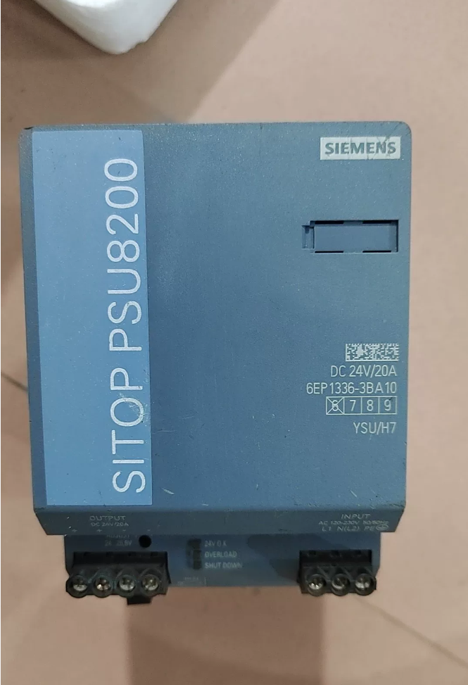

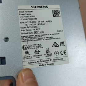
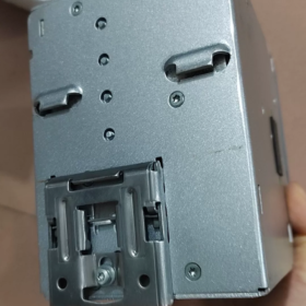
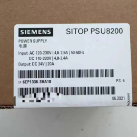
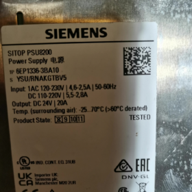
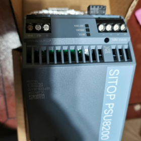
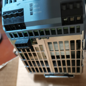
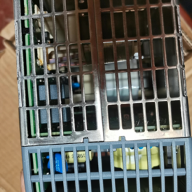
หมายเลขคำสั่งซื้อ: 6EP1336-3BA10
การกำหนดแบบเต็ม: SITOP PSU8200 /1ACDC /24VDC /20A แหล่งจ่ายไฟสลับโหมดอุตสาหกรรมราง DIN
เอาท์พุต: 24 VDC20A, 480 ว; รองรับการทำงานแบบขนานสำหรับการขยายกำลังและการทำงานซ้ำซ้อน
- ข้อมูลจำเพาะทางไฟฟ้าหลัก
ป้อนข้อมูล (อินพุตคู่ AC/DC ที่เป็นเอกลักษณ์สำหรับรุ่นนี้)
จัดอันดับ AC: 120-230 VAC, ช่วงการใช้งาน 85-275VAC, 50-60 เฮิรตซ์
จัดอันดับ DC: 110-220 กระแสตรง, ช่วงการทำงาน 88-350VDC
กระแสไฟเข้า: 2.5 @230VAC; 4.6 @120VAC
เวลารอ: ≥20ms ที่โหลดพิกัด
⚠️ จำเป็นต้องลดกำลังไฟฟ้าเมื่อแรงดันไฟฟ้าอินพุต <100V
เอาท์พุต
ที่กำหนด: 24 กระแสตรง / 20 ก
ช่วงที่ปรับได้: 24.0-28.8 กระแสตรง (โพเทนชิออมิเตอร์ที่แผงด้านหน้าสำหรับการชดเชยแรงดันไฟฟ้าตกที่สายยาว)
ฟังก์ชั่นเพิ่มพลัง: กระแสไฟฟ้าที่กำหนดสูงสุด 3 เท่า (60 ก) สำหรับโหลดแบบพุ่งเข้า เช่น มอเตอร์และรีเลย์สตาร์ท; โหมดกระแสคงที่ที่เลือกได้หรือการปิดระบบล็อคเมื่อลัดวงจร
เอาต์พุตแยกทางไฟฟ้า; ป้องกันการลัดวงจร, โอเวอร์โหลด, แรงดันไฟฟ้าเกินและอุณหภูมิสูงเกินไป; การกู้คืนอัตโนมัติหลังจากปิดเครื่องเกินอุณหภูมิ
ประสิทธิภาพ: ประมาณ. 93%-94%
ขั้วสัญญาณ
- 24หน้าสัมผัสรีเลย์ V-OK (13-14): การสัมผัสแบบแห้งโดยปราศจากศักยภาพ, ปิดเมื่อแหล่งจ่ายไฟทำงานตามปกติ, สำหรับการวินิจฉัยสถานะ PLC
- เปิด/ปิดระยะไกล (15-16): การติดต่อที่ไม่มีศักยภาพสำหรับการเปิดใช้งานระยะไกลภายนอก / การปิดใช้งานเอาต์พุต 24V
- เครื่องกล & ข้อมูลสิ่งแวดล้อม
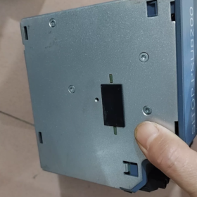
การติดตั้ง: ติดตั้งเข้ากับราง DIN มาตรฐาน, ที่อยู่อาศัยโลหะ, การระบายความร้อนด้วยการพาความร้อนตามธรรมชาติโดยไม่ต้องใช้พัดลม
ขนาด: กว้าง 90 มม. × สูง 125 มม. × ลึก 125 มม
น้ำหนัก: ประมาณ. 1.2 กก
ระดับการป้องกัน: IP20 (สำหรับการใช้งานแบบติดตู้เท่านั้น)
อุณหภูมิในการทำงาน: -25℃~+70℃; ลดลงเหนือ 60 ℃; สูงสุด. 75 % โหลดที่ 70 ℃
การกวาดล้างการกระจายความร้อน: ระยะห่างด้านบน ≥50มม & ด้านล่าง; อาจติดตั้งยูนิตติดกันอย่างแน่นหนา
การรับรอง: ซีอี, UL/cUL, ซีซีซี, การอนุมัติทางทะเลของ GL, RoHS
III. วิวัฒนาการของโมเดล & ตัวเลือกการทดแทน
- ทดแทนรุ่นก่อนโดยตรง: 6EP1336-3BA00 (ยกเลิกแล้ว)
6EP1336-3BA10 เป็นเวอร์ชันปรับปรุงฮาร์ดแวร์, ปักหมุด, มิติต่อมิติ, การเปลี่ยนแบบดรอปอินที่เข้ากันได้กับฟังก์ชัน, ด้วยประสิทธิภาพที่สูงขึ้นและประสิทธิภาพแรงดันไฟฟ้าอินพุตต่ำที่ได้รับการปรับปรุง.
- โปรเจ็กต์ใหม่ ซีรีส์ SITOP PSU6200 เจเนอเรชั่นใหม่: 6EP3336-8SB00-0AY0
บันทึก: 6EP3336-8SB00-0AY0 รองรับอินพุต AC เท่านั้น, ไม่มีความสามารถในการอินพุต DC. ไม่รองรับฮาร์ดแวร์; การกำหนดเทอร์มินัลจะแตกต่างกัน, ให้ความสนใจในระหว่างการเลือก.
- โมดูลส่วนขยายที่เข้ากันได้ (ระบบโมดูลาร์ PSU8200)
เข้ากันได้โดยตรงกับส่วนเสริมแบบโมดูลาร์ SITOP โดยไม่ต้องใช้อะแดปเตอร์เพิ่มเติม:
โมดูลบัฟเฟอร์: 6EP1961-3BA21; โมดูลสำรอง DC-UPS
โมดูลความซ้ำซ้อน: 6EP1961-3BA00; สำหรับการจ่ายไฟซ้ำซ้อนแบบสองกำลัง
โมดูลหัวกะทิ: 6EP1961-3BA31, การป้องกันการจำกัดกระแสไฟสาขา 24V แบบหลายช่องสัญญาณ; การลัดวงจรที่สาขาเดียวจะไม่ทำให้บัสบาร์ 24V ทั้งหมดพัง
- สถานการณ์การใช้งานทั่วไป
ตู้ควบคุม PLC, วิทยาการหุ่นยนต์, เครื่องมือกล, ท่าเรือ & อุปกรณ์ทางทะเล, กระบวนการอัตโนมัติ. เหมาะสำหรับระบบที่ต้องการอินพุตคู่ AC/DC (เช่น. แหล่งจ่ายไฟ DC สำรอง), โหลดไหลเข้าสูง, การตอบสนองสถานะพลังงานและการควบคุมการเปิด/ปิดจากระยะไกล.
- แนวทางการเดินสายไฟ
- ขั้วอินพุต: L1, เอ็น(L2), วิชาพลศึกษา; รองรับไฟ AC เฟสเดียว, ประปาสองเฟสจากไฟหลักสามเฟส, หรืออินพุต DC
- เอาท์พุต: ขั้วต่อสกรูชุดคู่สำหรับ +24V และ 0V. ขนานทั้งสองชุดเมื่อกระแสเอาต์พุต> 15A สำหรับการแชร์กระแสและการป้องกันความร้อน
- ขั้วสัญญาณ: 13-14 ข้อเสนอแนะสถานะ; 15-16 เปิด/ปิดระยะไกล; ทั้งสองเป็นผู้ติดต่อที่ไม่มีศักยภาพ, ห้ามต่อวงจรไฟฟ้าแรงสูง
- แรงดันขาออกเริ่มต้นจากโรงงานคือ 24V. ปรับแบบละเอียดเป็น 26-28V เพื่อการชดเชยการตกของสายเคเบิลยาว; ไม่เกินแรงดันไฟฟ้าของอุปกรณ์ปลายน้ำ.
คำแนะนำในการติดตั้งสำหรับ ซีเมนส์ 6EP1336-3BA10 (PSU8200-20A)
- ประเภทการติดตั้ง
การติดตั้งมาตรฐาน: สอดคล้องตามมาตรฐาน DIN-rail EN60715 (TS35-7.5 / TS35-15, 35 รางมม) การติดตั้งสแน็ปอิน
คลิปสปริงในตัวที่ด้านหลัง, การติดตั้งโดยไม่ต้องใช้เครื่องมือ. ปล่อยคันโยกที่ด้านล่าง; ดันคันโยกลงเพื่อถอดยูนิตออกจากราง.
❌ ไม่รองรับการติดตั้งบนผนังโดยใช้สกรูยึดโดยตรง. การติดตั้งบนราง DIN เท่านั้น.
ระดับการป้องกัน IP20, สำหรับการติดตั้งตู้ภายในเท่านั้น; ไม่ใช่สำหรับการใช้งานกลางแจ้งแบบเปลือยเปล่า.
- การวางแนวการติดตั้ง (จำเป็นสำหรับประสิทธิภาพการระบายความร้อน & อายุการใช้งาน)
การพาความร้อนตามธรรมชาติแบบไม่ใช้พัดลม; การวางแนวไม่สามารถเปลี่ยนแปลงได้โดยพลการ
- ตำแหน่งมาตรฐาน: การติดตั้งในแนวตั้ง, ขั้วคว่ำหน้าลง (ป้อนข้อมูล & ขั้วต่อเอาต์พุตที่ด้านล่างของตัวเครื่อง), หน่วยตั้งตรง. นี่เป็นตำแหน่งเดียวที่เป็นทางการสำหรับการดำเนินการโหลดเต็มอย่างต่อเนื่อง.
- ❌ต้องห้าม: แนวนอนด้านข้าง, คว่ำลง (ขั้วขึ้น), การติดตั้งแบบเอียง. การวางแนวที่ไม่ได้มาตรฐานจะทำให้การระบายความร้อนลดลงและต้องมีการลดพิกัดภาระหนัก; ไม่แนะนำสำหรับการปรับใช้ภาคสนาม.
- ข้อกำหนดการระบายความร้อน (วิกฤต)
| ทิศทาง | การกวาดล้างที่จำเป็น | หมายเหตุ |
| สูงสุด | ≥50มม | ปล่อยให้อากาศร้อนไหลขึ้นด้านบน; การเดินสายไฟจะต้องไม่ครอบครองพื้นที่นี้ |
| ด้านล่าง | ≥50มม | ช่องรับอากาศเย็น; การเดินสายไฟต้องไม่กีดขวางพื้นที่ด้านล่าง |
| ซ้าย / ขวา | 0 มม | สามารถติดตั้งหลายยูนิตติดกันได้อย่างแน่นหนา, ไม่จำเป็นต้องมีช่องว่างจากด้านหนึ่งไปอีกด้าน |
อย่าติดตั้งส่วนประกอบที่สร้างความร้อนเหนือแหล่งจ่ายไฟโดยตรง. ลดภาระเมื่อสภาพแวดล้อมภายในตู้ > 60 ℃.
- การติดตั้ง & ขั้นตอนการกำจัด
- ขอเกี่ยวสลักด้านบนของคลิปสปริงด้านหลังเข้ากับราง DIN.
- กดส่วนล่างเข้าหารางจนกระทั่งได้ยินเสียง “คลิก” ยืนยันการติดคลิป.
- เขย่าเบา ๆ เพื่อตรวจสอบการนั่งที่มั่นคงจากการสั่นสะเทือน.
- การกำจัด: กดคันโยกปลดล็อคสีดำที่ด้านล่างลง, แกว่งส่วนล่างออกไปด้านนอก, ยกหน่วยออกจากราง.
สำหรับสภาพแวดล้อมที่มีการสั่นสะเทือนสูง: ติดตั้งตัวหยุดปลายราง DIN เพื่อป้องกันการเคลื่อนที่เลื่อน.
- การเดินสายไฟเทอร์มินัล & ค่าแรงบิด
ดำเนินการเดินสายไฟโดยตัดการเชื่อมต่อไฟฟ้า.
อินพุต L/N/PE: 0.2-4 ตัวนำ mm², แรงบิดในการขัน 0.5-0.6N·m
เอาท์พุต +24V /0V: คู่เทอร์มินัลคู่; ขนานทั้งสองคู่สำหรับกระแส > 15A เพื่อลดความร้อน
ขั้วสัญญาณ 13-14 (ตกลงข้อเสนอแนะ), 15-16 (เปิด/ปิดระยะไกล): 0.14-1.5 ลวดละเอียด mm², แรงบิด 0.5-0.6N·m
- การติดตั้งแบบขนาน / โมดูลสำรอง
แหล่งจ่ายไฟนี้สามารถติดตั้งแบบเคียงข้างกันอย่างแน่นหนาบนราง DIN พร้อมโมดูลส่วนขยาย SITOP ที่ใช้งานร่วมกันได้ (ความซ้ำซ้อน, บัฟเฟอร์, โมดูลหัวกะทิ). ไม่จำเป็นต้องมีช่องว่างด้านความร้อนระหว่างแหล่งจ่ายไฟและโมดูลเสริม.
- ข้อห้ามในการติดตั้ง
- ห้ามติดตั้งยูนิตภายในรางด้านล่างแบบปิดในตู้; ช่องว่างด้านบน/ล่างที่ถูกบล็อกนำไปสู่การปิดเครื่องที่อุณหภูมิเกิน.
- ห้ามติดตั้งแบบกลับหัวหรือแนวนอน.
- อย่าวางอุปกรณ์ที่ใช้ความร้อนสูงไว้เหนือตัวเครื่องโดยตรง.
- ใช้ตู้ในอาคารเท่านั้น; หลีกเลี่ยงสภาพแวดล้อมแบบเปิดโล่งและมีความชื้นสูงที่ไม่มีการป้องกัน.
6EP1336-3BA10 (PSU8200-20A) ขนาน / แนวทางการทำซ้ำซ้อน + รายการตรวจสอบการแก้ไขปัญหา
- การทำงานแบบขนานเพื่อการขยายกำลัง (ไม่มีการแยกความผิด)
สูงสุด. 5 หน่วยที่เหมือนกันขนานกันสำหรับการแชร์กระแสไฟฟ้าอัตโนมัติ. ต้องตั้งค่าสวิตช์ดิป A เป็นเปิดเพื่อเปิดใช้งานเส้นโค้งคุณลักษณะแบบขนาน.
- ข้อกำหนดเบื้องต้นของฮาร์ดแวร์: หมายเลขคำสั่งซื้อเดียวกัน 6EP1336-3BA10; รักษาการแก้ไขฮาร์ดแวร์ให้สอดคล้องกันหากเป็นไปได้.
- ข้อกำหนดการเดินสายไฟ
เชื่อมต่อ +24V และ 0V ของแต่ละยูนิตเข้ากับบัสบาร์เอาท์พุตทั่วไป. สายเคเบิลขั้วบวกต้องมีความยาวและหน้าตัดเท่ากันเพื่อให้อิมพีแดนซ์เท่ากันเพื่อการแบ่งปันกระแสไฟที่เหมาะสม.
ขั้วลบ 0V ทั้งหมดจะต้องต่อสายดินโดยทั่วไป; ไม่อนุญาตให้มีพื้นลอยน้ำ.
เบรกเกอร์อินพุตทั่วไปที่แนะนำสำหรับการสตาร์ท-สต็อปแบบซิงโครไนซ์.
ความแตกต่างแรงดันไฟฟ้าเอาท์พุตขณะไม่มีโหลดระหว่างแต่ละยูนิต ≤50mV (ค่าเริ่มต้นจากโรงงานตรงตามข้อกำหนด; ปรับเทียบใหม่หากมีการปรับโพเทนชิโอมิเตอร์แล้ว).
- การตั้งค่าดิปสวิตช์
เอ-ออน: โหมดขนาน (เพื่อขยายอำนาจ)
เอ-ปิด: โหมดหน่วยเดียว (ค่าเริ่มต้นจากโรงงาน; อย่าปิดการทำงานแบบขนาน)
- ข้อจำกัด: การขนานโดยตรงสำหรับการขยายกำลังไม่สามารถแยกข้อผิดพลาดได้. การลัดวงจรที่เอาต์พุตเดียวจะดึงบัสบาร์ 24V ทั้งหมดลง. ไม่ใช่สำหรับความซ้ำซ้อนที่ทนต่อข้อผิดพลาด.
- 1+1 อุปทานซ้ำซ้อน (แยกข้อผิดพลาด, โซลูชั่นทางวิศวกรรมที่แนะนำ)
PSU8200-20A สองยูนิตพร้อมโมดูลสำรอง 6EP1961-3BA00 (PSE202U) เพื่อการแยกตัวออกจากกัน. หากแหล่งจ่ายไฟตัวหนึ่งล้มเหลว, ส่วนที่สองรับภาระต่อโหลดได้อย่างราบรื่นโดยไม่มีการหยุดชะงักของบัส 24V.
- เค้าโครงราง DIN: แหล่งจ่ายไฟสองอัน + โมดูลสำรองที่ติดตั้งติดกันอย่างแน่นหนา; ขั้วทั้งหมดคว่ำหน้าลง; ไม่จำเป็นต้องมีการกวาดล้างจากด้านหนึ่งไปอีกด้านหนึ่ง.
- ประเด็นสำคัญของการเดินสายไฟ
- ป้อนแหล่งจ่ายไฟสองตัวจากวงจรอินพุตอิสระเพื่อความน่าเชื่อถือด้านสำรองสูงสุด.
- เชื่อมต่อเอาต์พุต 24V+ ของแหล่งจ่ายไฟแต่ละตัวเข้ากับช่องอินพุตสองช่องของโมดูลสำรอง.
- เชื่อมต่อขั้วต่อ 0V ของทั้งแหล่งจ่ายไฟและโมดูลสำรองได้อย่างน่าเชื่อถือสำหรับการเชื่อมต่อที่มีศักย์ไฟฟ้าเท่ากัน; ขั้นตอนนี้เป็นข้อบังคับ.
- กำหนดเส้นทางเอาต์พุตโมดูลสำรองไปยังบัสบาร์โหลด 24V ของฟิลด์.
- โมดูลสำรองมีหน้าสัมผัสรีเลย์ข้อบกพร่อง, เชื่อมต่อกับอินพุตดิจิตอล PLC เพื่อแจ้งเตือนข้อผิดพลาดซ้ำซ้อน.
- การตั้งค่าดิปสวิตช์: สำหรับการกำหนดค่าซ้ำซ้อน, ตั้งสวิตช์ดิป A ของแหล่งจ่ายไฟไปที่ปิด (โหมดหน่วยเดียว). อย่าเปิดใช้งานโหมดขนาน.
⚠️ ห้ามใช้ระบบสำรองแบบขนานโดยตรงโดยไม่มีโมดูลสำรอง. การลัดวงจรภายในหนึ่งยูนิตจะทำให้ระบบ 24V เสียหายทั้งหมด.
III. ตารางอ้างอิงตัวบ่งชี้ LED
| สถานะ LED | ความหมาย | การกระทำ |
| สีเขียวคงที่ | หน่วยสุขภาพดี, เอาท์พุต > 20V | การทำงานปกติ |
| สีเหลืองคงที่ | โอเวอร์โหลด / ขีดจำกัดกระแสคงที่ทำงานอยู่, เปิดใช้งาน Power-Boost | ตรวจสอบกระแสโหลด; ค้นหาการลัดวงจรบางส่วน; ลดภาระ |
| สีแดงคงที่ | การปิดระบบล็อค (ลัดวงจร / แรงดันไฟฟ้าเกิน / เกินอุณหภูมิ) | ปิดเครื่องเป็นเวลา ≥60วินาที, หรือยกเลิกการยืนยันรีโมท 15-16 เป็นเวลา ≥5 วินาทีเพื่อรีเซ็ต; กำจัดการลัดวงจร / สาเหตุของความร้อนมากเกินไป |
| ไฟ LED ทั้งหมดดับลง | ไม่มีแหล่งจ่ายอินพุต; ฟิวส์ภายในขาด | ตรวจสอบแรงดันไฟฟ้าอินพุต AC/DC และการต่อสายดิน PE |
ดิปสวิตช์ B: การเลือกการตอบสนองการลัดวงจร
บี-ออฟ (ค่าเริ่มต้นจากโรงงาน): โหมดกระแสคงที่, 23 การจำกัดการลัดวงจร; การกู้คืนอัตโนมัติหลังจากล้างข้อผิดพลาด; ไฟ LED สีเหลืองสว่าง
บีออน: โหมดการปิดระบบล็อค; เอาท์พุตจะตัดเมื่อไฟฟ้าลัดวงจร; ไฟ LED สีแดงสว่างขึ้น; จำเป็นต้องรีเซ็ตวงจรพลังงาน
- รายการตรวจสอบการแก้ไขปัญหา
- ไม่มีไฟ LED แสดงสถานะหลังจากเปิดเครื่อง, เอาต์พุตเป็นศูนย์
- วัดแรงดันไฟฟ้าอินพุต L-N: กระแสสลับ 85-275VAC / กระแสตรง 88-350VDC; ยืนยันการเชื่อมต่อสายดินป้องกัน PE.
- ตรวจสอบแรงบิดของขั้วต่อสกรูว่ามีหน้าสัมผัสหลวมหรือไม่; ตรวจสอบสถานะเบรกเกอร์ต้นทาง.
- หากแรงดันไฟฟ้าขาเข้าเป็นปกติ แต่ไม่มีไฟ LED: ฟิวส์อินพุตภายในล้มเหลว; ความผิดพลาดของฮาร์ดแวร์, เปลี่ยนแหล่งจ่ายไฟ.
- ไฟ LED สีเหลืองติดค้าง, เอาต์พุตลดลงเหลือ 18-20V
- กระแสโหลดเกิน 20A → โหมดจำกัดกระแสคงที่; วัดกระแสโหลดทั้งหมดตามจริง.
- ความเสียหายจากการลัดวงจรหรือฉนวนสายเคเบิลบางส่วนที่ด้านเอาต์พุต. ปลดโหลดทั้งหมด; ตรวจสอบว่าแรงดันไฟฟ้ากลับคืนสู่ 24V ภายใต้สภาวะไม่มีโหลดหรือไม่.
- แรงดันไฟฟ้าตกมากเกินไปเกิดจากสายเคเบิลแบบบางในระยะไกล; ใช้ตัวนำเอาต์พุตที่มีขนาดใหญ่กว่าหรือเพิ่มแรงดันเอาต์พุตเล็กน้อยผ่านโพเทนชิออมิเตอร์เพื่อชดเชย.
- ไฟ LED สีแดงปิดล็อคเมื่อเปิดเครื่อง, ไม่มีเอาต์พุต
- การลัดวงจรด้านเอาท์พุต. ทดสอบโดยตัดการเชื่อมต่อโหลดทั้งหมด; พฤติกรรมไม่มีโหลดปกติบ่งชี้ว่าโหลดภายนอกลัดวงจร.
- อุณหภูมิแวดล้อมตู้มากเกินไป, การระบายอากาศด้านบน/ล่างไม่เพียงพอทำให้เกิดการป้องกันอุณหภูมิเกิน; ยืนยันด้านบน≥50มม & การกวาดล้างด้านล่าง.
- แรงดันไฟขาออกเกิน: ตรวจสอบให้แน่ใจว่าโพเทนชิออมิเตอร์ไม่ได้ถูกปรับเกิน 28.8V โดยไม่ได้ตั้งใจ; ยืนยันพิกัดแรงดันไฟฟ้าของอุปกรณ์ดาวน์สตรีม.
- ขั้นตอนการรีเซ็ต: ปิดเครื่อง ≥60 วินาที จากนั้นเปิดเครื่องอีกครั้ง; หรือเปิดรีโมท 15-16 เป็นเวลา ≥5 วินาที จากนั้นปิดอีกครั้ง.
- ผิดปกติ 24V-OK (13-14) พฤติกรรมหน้าสัมผัสรีเลย์
เทอร์มินัล 13-14 เป็นหน้าสัมผัสแห้งที่ปราศจากศักย์ไฟฟ้า, ปิดเฉพาะเมื่อเอาต์พุต> 20V. การจัดอันดับการติดต่อ: ดีซี30วี, สูงสุด. 0.1 ก. สำหรับสัญญาณอินพุตดิจิตอล PLC เท่านั้น; อย่าขับคอยล์คอนแทคเตอร์หรือโหลดที่มีกำลังสูง.
- การแบ่งปันกระแสไม่ดีในแบบคู่ขนาน; เครื่องหนึ่งร้อนเกินไป
- Dip-switch A ไม่ได้ตั้งค่าเป็น ON.
- ความยาวไม่เท่ากันมาก / ภาพตัดขวางของสายเคเบิลเอาต์พุตขั้วบวก.
- ความแตกต่างของแรงดันเอาต์พุตขณะไม่มีโหลด > 50mV ระหว่างยูนิต; ปรับแต่งโพเทนชิโอมิเตอร์เพื่อการจับคู่.
- การเดินสายไฟ 0V ที่หลวม ส่งผลให้ศักย์ไฟฟ้าไม่ตรงกัน.
- เทอร์มินัลระยะไกล 15-16 ล้มเหลวใน / ออกจากการควบคุม
15-16 เป็นผู้ติดต่อที่ไม่มีศักยภาพ: ลัดวงจร = เปิดใช้งานเอาต์พุต; open-circuit = ปิดใช้งานเอาต์พุต. ไม่จำเป็นต้องใช้แหล่งจ่ายไฟภายนอก.
หากไม่ได้ใช้ฟังก์ชันระยะไกล: เก็บ 15-16 ลัดวงจรด้วยจัมเปอร์จากโรงงาน; อย่าถอดจัมเปอร์ออก.
- คำแนะนำการว่าจ้าง
- การว่าจ้างคณะรัฐมนตรีใหม่: เปิดเครื่องโดยไม่ต้องโหลดก่อน; ยืนยันเอาต์พุต 24V และ LED OK สีเขียวคงที่; เชื่อมต่อโหลดแบบค่อยเป็นค่อยไป.
- การว่าจ้างระบบสำรอง: ตัดการเชื่อมต่อแหล่งอินพุตครั้งละหนึ่งแหล่ง; ตรวจสอบการสับเปลี่ยนอย่างราบรื่นโดยไม่มีการหยุดโหลด.
- การใช้งานตู้อุณหภูมิสูง: ใช้การลดพิกัดโหลดที่สูงกว่า 60°C โดยรอบ; หลีกเลี่ยงการทำงานเต็ม 20-A อย่างต่อเนื่อง.





NH42-63-318x560.png "สวิตช์ถ่ายโอนอัตโนมัติชนิด CHINT PC (เอทีเอส)NH42-63/4SZ")



