 المقاولين,قاطع الدائرة,الاستشعار,التشفير,بلك,محول

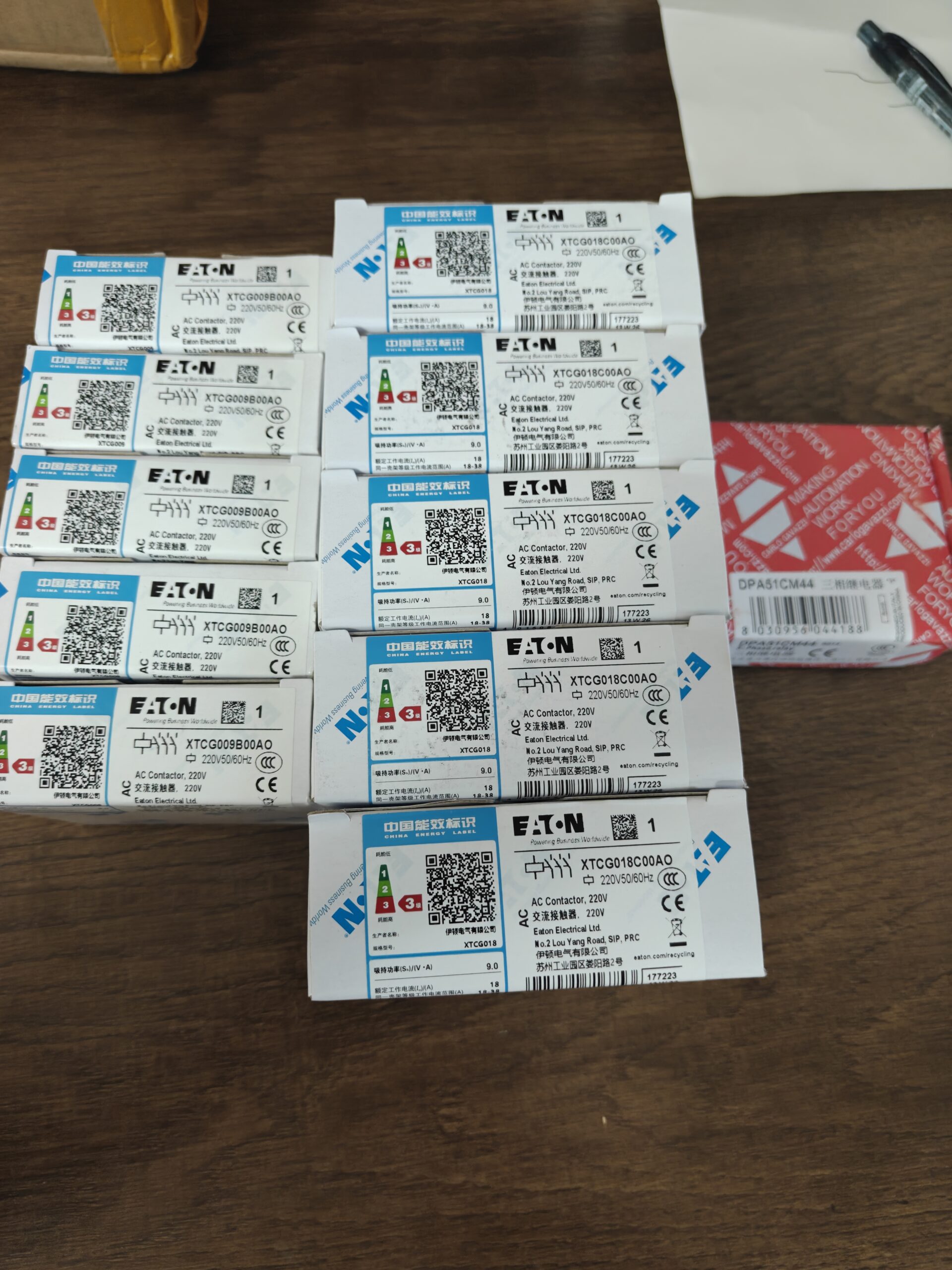

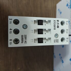
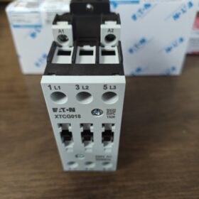
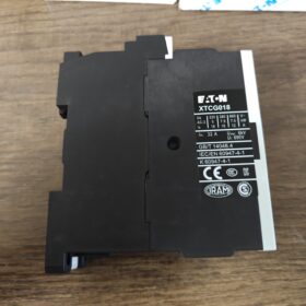
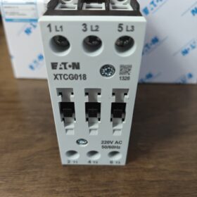
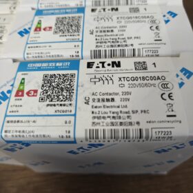
ملحوظة: The last character is letter O, لا رقم 0; belongs to XTCG sub-series of Eaton XT-range IEC المقاولين.
فك رمز النموذج
| مقطع الكود | وصف |
| XT | إيتون XT‑range IEC control series |
| ج | المقاولين |
| ز | XTCG series, screw‑terminated 3‑pole motor contactor |
| 18 | AC‑3 rated operational current:18A for main circuit |
| ج | Frame size C, 45 mm width housing |
| 0 | No built‑in auxiliary contacts (0لا + 0NC) |
| إلى | لفائف: AC220V 50/60Hz (أ = التيار المتردد, O=code for 220VAC coil) |
Full definition: 3-القطب, AC-3 18A, no-built-in auxiliary contacts, لفائف AC220V, screw-terminal AC contactor.
المعلمات الكهربائية الأساسية
| غرض | مواصفة |
| Main Poles | 3P‑NO (three normally‑open main contacts) |
| AC‑3 Rated Operational Current | 18A @400V motor load |
| AC‑1 Resistive Load | 32أ |
| Rated Insulation Voltage Ui | 690V |
| الجهد لفائف | AC220V 50/60Hz |
| جهات الاتصال المساعدة | None onboard; external accessories XTCGXF*** required |
| التحمل الميكانيكي | ≥10 000 000 operations |
| AC‑3 Electrical Endurance | ≥1 000 000 operations |
| تصاعد | DIN35 rail mounting or screw‑on backplate mounting |
| المحطات | Screw‑clamp terminals |
| الشهادات | سي سي سي, م, أول, وكالة الفضاء الكندية, IEC60947‑4‑1 |
بدني & الظروف البيئية
Housing width: 45 مم
درجة حرارة التشغيل:-25درجه مئوية ~ +60 درجه مئوية, condensation and icing forbidden
درجة حرارة التخزين:-40درجه مئوية ~ +85 درجه مئوية
وزن: تقريبا. 0.21 كجم
سيناريوهات التطبيق النموذجية
- Three-phase motor start-stop control (≤7.5kW @400V motor)
- المشجعين, مضخات المياه, الناقلات, ضواغط الهواء, آلات التعبئة والتغليف
- التدفئة والتهوية وتكييف الهواء & cabinet OEM assembly; can be paired with XTOD thermal overload relay for motor overload protection
List of Compatible Accessories
Auxiliary contact block: XTCGXFAC (1NO+1NC etc.), side-mounted
Thermal overload relay: XTOD018 (0.1-18A motor protection coverage)
Mechanical interlock module: XTCG-MV, for reversing circuit
Surge suppressor: RC / varistor module for coil side
Direct-Replacement Models & ملاحظات الاستبدال
- Same-series alternative: XTCG018C00DT (different coil code; verify coil voltage, not a drop-in replacement)
- Cross-series alternative: XTCE018C00A0 (Eaton XTCE series, functionally equivalent; check accessory compatibility)
⚠️Pitfall reminder: XTCG018C00AO has no onboard auxiliary contacts. External auxiliary-contact accessory must be fitted if PLC feedback signals are required, otherwise control circuits cannot function.
Non-Applicable Operating Conditions
Switching frequency>1200 cycles/hour
Heavy corrosive gas / heavy dust environment without proper protection
DC-coil applications (this unit is AC-coil type)
Brief Wiring Instructions
- الدائرة الرئيسية: L1-L2-L3 supply side; T1-T2-T3 load (محرك) جانب
- Coil terminals A1/A2 connect to AC220V
- No built-in auxiliary contacts; all logic feedback signals shall be obtained from externally fitted auxiliary-contact accessories.
XTCG018C00AO (Frame C) تصاعد & الأبعاد الشاملة (وحدة: مم)
All XTCG-C frame models (009-032أ) share identical housing dimensions. Supports DIN35 rail mounting AND screw-on back-plate mounting.
الأبعاد الشاملة (without fitted accessories)
| غرض | قيمة | ملاحظات |
| Width W | 45 | Reference for cabinet layout spacing |
| Height H | 85 | Total height including upper & lower terminals |
| Depth D | 97.4 | Depth inside cabinet panel after rail‑mounted |
Overall dimension: 45(دبليو) × 85(ح) × 97.4(د) مم
Screw-on back-plate cut-out dimensions (DIN rail unused, direct screw-fix onto cabinet back-plate)
Horizontal mounting-hole centre-to-centre spacing: 35 مم
Vertical mounting-hole centre-to-centre spacing: 76 مم
Fastener hole diameter: Φ4.5 (مسامير M4)
Hole-to-edge margin: approx.4.5 mm top & قاع.
DIN Rail Installation Information
- Standard DIN-35-7.5 rail (universal electrical 35 mm rail)
- Back-side snap-in clip for direct rail-clip mounting; tool-free assembly & التفكيك.
⚠️Dimension change after accessory installation
- Side-mount auxiliary-contact block XTCGXF: width increases by 10 mm, total width 55 mm
- Bottom-mount thermal overload relay XTOD: overall height increases by approx.42.5 mm
- Mechanical interlock XTCG-MV: two contactors side-by-side with zero gap; total width = direct sum (45+45=90 mm)
Installation Boundary Conditions
- Cooling clearance: ≥10 mm top & قاع; no mandatory clearance side-to-side (multiple units may be mounted adjacent to each other)
- Do not mount tightly against closed cabinet partitions; ambient temperature-25℃~+60℃, condensation prohibited.
- Maximum permitted conductor size: main circuit 6 mm²; coil circuit 2.5 mm².
Cross-model reference
Models XTCG009C / XTCG025C / XTCG032C share identical housing, cut-out and rail-mount dimensions; only internal contact current rating differs. Varied coil voltage codes (AO/DT etc.) produce no change in physical dimensions.
Operating Voltage Differentiation for Eaton XTCG018C00AO
Two separate voltage systems exist for contactors: الدائرة الرئيسية (الاتصالات الرئيسية) and coil control circuit. Do not confuse them.
- Coil Control Voltage (suffix code AO)
Coil rated voltage: AC 220V 50/60Hz
المحطات: أ1, A2
Permissible coil operating voltage range: 0.85~1.1×Ue, i.e. AC187V ~ AC242V
⚠️This is an AC coil. DC supply is strictly forbidden.
- الدائرة الرئيسية (main contacts for motor loads)
| المعلمة | قيمة |
| تصنيف الجهد التشغيلي Ue | الأعلى. AC690V |
| Common operating voltages | تيار متردد 230 فولت / 400V / 500V / 690V |
| تصنيف الجهد العزل واجهة المستخدم | 690V |
| Impulse withstand voltage Uimp | 6 كيلو فولت |
The 18A AC-3 rating is specified at 400V. Main circuit can operate within 0-690V AC; allowable current varies with applied voltage.
Key Supplementary Notes
- Suffix code `AO` exclusively denotes AC220V coil. Changing suffix code (على سبيل المثال. DT=AC380V) only alters coil voltage; main-circuit voltage capability remains unchanged.
- Voltage outside permitted coil operating range causes faults: undervoltage → pull-in failure / chattering; overvoltage → coil overheating & الإرهاق.
- Main-circuit current derating applies at elevated ambient temperatures.
XTCG018C00AO Coil Troubleshooting Guide
Coil specification: AC220V 50/60Hz; Terminals A1/A2; permissible operating range AC187V-242V; DC supply prohibited.
عيب 1: Contactor does not pull-in at all, zero acoustic response
Probable Root-Causes
- No voltage on control circuit: 0V measured across A1/A2; upstream relay / مخرج PLC / فتيل / سلك مكسور / loose terminal.
- Coil supply voltage below 0.85Ue (<187V): insufficient voltage for pull-in.
- Coil open-circuit burnout: infinite resistance reading between A1-A2 via multimeter.
- الاستيلاء الميكانيكي: foreign-object ingress, corroded iron-core, mis-fitted add-on accessories causing mechanical jamming.
Remedial Steps
- Power-off safety confirmation; measure live voltage across A1/A2 terminals.
- انقطاع التيار الكهربائي; disconnect coil wiring; measure DC resistance of coil standalone. Typical resistance of C-frame AC220V coil: 1300-1500 أوه. Infinite resistance = burned-open coil; near-zero resistance = short-circuited coil.
- Manually actuate contactor armature; verify smooth movement. If sticking, remove foreign debris; inspect fit of auxiliary-contact / interlock accessories.
- Verify continuity of control-circuit fuse, PLC outputs and intermediate relays.
عيب 2: Contactor chatters / loud buzzing noise, unstable pull-in
Probable Root-Causes
- Marginal low coil voltage; long-run / thin-gauge control wiring creates excessive voltage drop.
- Iron-core mating surfaces contaminated with oil, dust or iron-particles; enlarged magnetic air-gap.
- Supply-waveform distortion, harmonic distortion caused by VFD interference.
- Degraded coil with partial turn-to-turn short-circuit.
Remedial Steps
- Live measurement of A1/A2 voltage; must stay within AC187-242V. Increase control-cable cross-section for long-distance control loops.
- انقطاع التيار الكهربائي; clean iron-core mating surfaces of iron-dust and debris. Do NOT apply lubricant grease or oil.
- قياس مقاومة الملف; significantly-lower-than-nominal resistance indicates turn-to-turn short-circuit; replace full contactor unit.
- Fit RC-type coil surge suppressor in case of severe electromagnetic interference.
Fault3: Coil persistent overheating / rapid burnout
Probable Root-Causes
- Wrong supply voltage: AC380V applied to AC220V coil — most frequent burnout cause.
- Continuous supply voltage>1.1Ue (>242V), long-term over-voltage operation.
- Mechanical jamming prevents full armature closure; large residual air-gap keeps coil current high continuously.
- Accidental DC power supply to AC coil: instant burnout.
Remedial Steps
- Double-check actual supply voltage; match AO-coded AC220V coil rating strictly.
- Verify free mechanical movement; confirm full armature closure.
- Confirm AC-only supply; never drive with DC source.
Burnt-out coil: XTCG-series coils are non-field-replaceable individually. Replace complete contactor assembly.
Fault4: Contactor fails to release after de-energization (stuck closed)
Distinguish main-contact welding versus coil residual-voltage / mechanical-seizure non-release.
- Residual voltage persists across A1/A2 after coil de-energization (PLC leakage current, residual voltage from parallel indicator lamps).
- الاستيلاء الميكانيكي; return-spring fatigue.
- Main-circuit short-circuit event resulting in welded main contacts.
Remedial Steps
- Measure residual voltage across de-energized A1/A2. Residual>30V prevents release; fit RC snubber for voltage dissipation.
- Disconnect main-circuit power; test manual return-action of mechanism. Replace unit if spring failure occurs.
- Inspect main-contacts for burn-welding. Welded contacts require full-unit replacement; do not refurbish by polishing contacts for continued service.
⚠️Hard-forbidden Operations
- Never apply DC voltage to AC220V AC-coil; instant burnout risk.
- Do not short-circuit terminals A1/A2 for test purposes.
- Do not repeatedly apply power to already-burned coil; secondary cabinet-damage risk.
- Never apply oil / grease onto iron-core mating surfaces; oil traps ferrous dust and causes buzzing / stuck-closed failure.
Quick-Reference Test Matrix
| Measurement Item | Acceptable Reference Value | Fault Judgment |
| Live coil operating voltage | AC187‑242V | <187V: pull‑in failure;>242V: overheating burnout |
| Coil DC resistance(A1‑A2) | 1300‑1500 Ω | Infinite = open‑circuit; far‑lower reading = turn‑to‑turn short‑circuit |
| Residual voltage A1‑A2 (power‑off) | <10 V | >30 V risk of release failure |
Supplementary note: No auxiliary contacts built-in. External side-mount auxiliary-contact block XTCGXF is mandatory for status feedback signals.








NH42-63-318x560.png "مفاتيح النقل التلقائي من نوع الكمبيوتر الشخصي CHINT (المنشطات الأمفيتامينية)NH42-63/4SZ")



